Digital Analog Converter (DAC_8B5V)
MC9S12G Family Reference Manual Rev.1.27
NXP Semiconductors 561
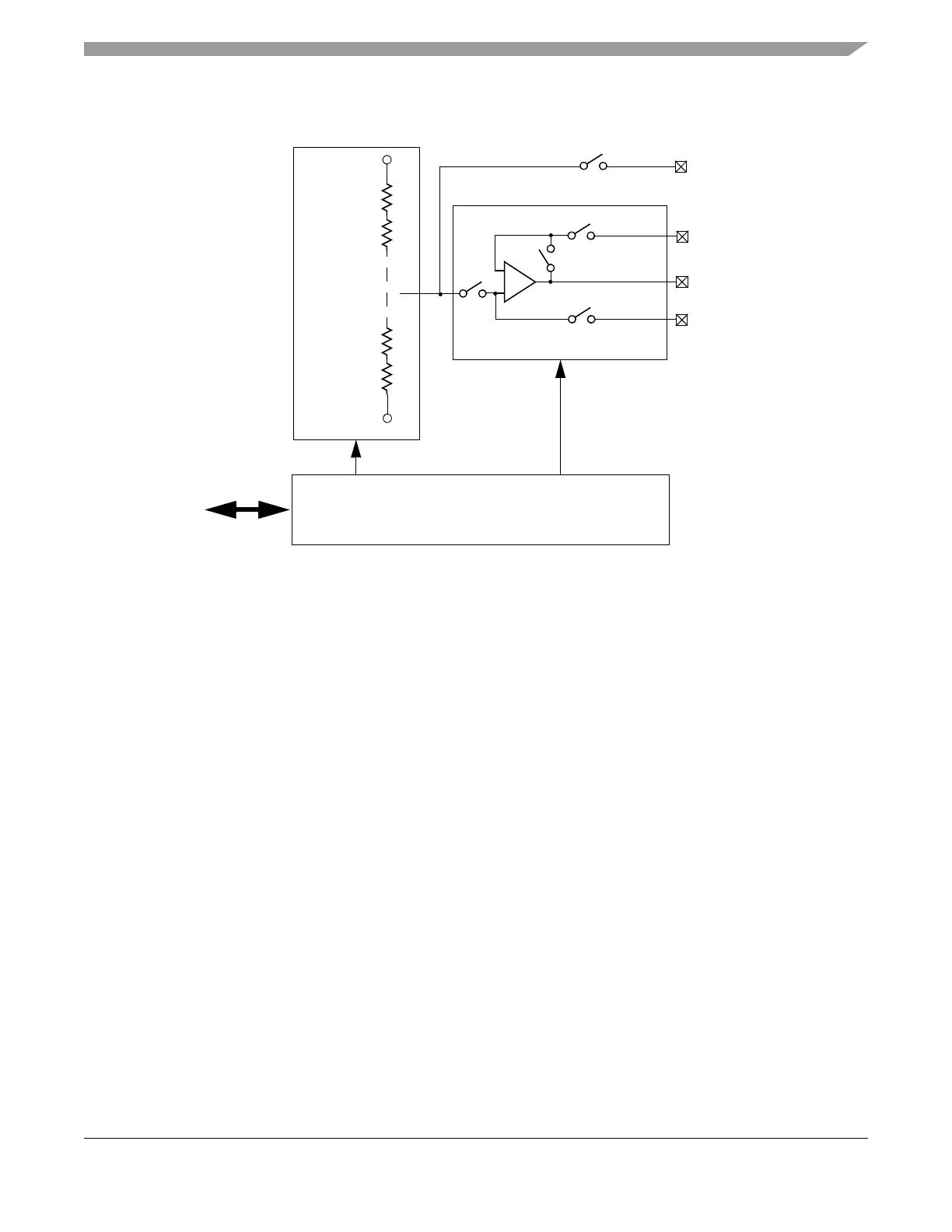
17.2.3 Block Diagram
Figure 17-1. DAC_8B5V Block Diagram
17.3 External Signal Description
This section lists the name and description of all external ports.
17.3.1 DACU Output Pin
This analog pin drives the unbuffered analog output voltage from the DAC resistor network output, if the
according mode is selected, see register bit DACM[2:0].
17.3.2 AMP Output Pin
This analog pin is used for the buffered analog output voltage from the operational amplifier output, if the
according mode is selected, see register bit DACM[2:0].
17.3.3 AMPP Input Pin
This analog input pin is used as input signal for the operational amplifier positive input pin, if the according
mode is selected, see register bit DACM[2:0].
+
–
Internal
Bus
Operational Amplifier
Resistor
Network
DACU
AMPM
AMP
AMPP
S1
S1
S2
S2
Configuration
Registers
DAC
S3
VRH
VRL

 Loading...


