EasyManuals Logo

NXP Semiconductors MC9S12G User Manual

NXP Semiconductors MC9S12G
1277 pages
To Next Page IconTo Next Page
To Previous Page IconTo Previous Page
Page #737 background imageLoading...
Page #737 background image
Timer Module (TIM16B8CV3)
MC9S12G Family Reference Manual Rev.1.27
NXP Semiconductors 739
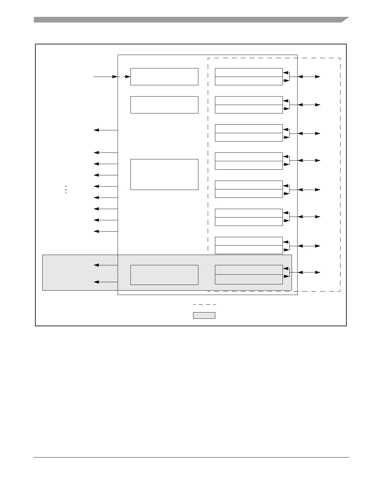
Figure 23-1. TIM16B8CV3 Block Diagram
Prescaler
16-bit Counter
Input capture
Output compare
16-bit
Pulse accumulator
IOC0
IOC2
IOC1
IOC5
IOC3
IOC4
IOC6
IOC7
PA input
interrupt
PA overflow
interrupt
Timer overflow
interrupt
Timer channel 0
interrupt
Timer channel 7
interrupt
Registers
Bus clock
Input capture
Output compare
Input capture
Output compare
Input capture
Output compare
Input capture
Output compare
Input capture
Output compare
Input capture
Output compare
Input capture
Output compare
Channel 0
Channel 1
Channel 2
Channel 3
Channel 4
Channel 5
Channel 6
Channel 7
Maximum possible channels, scalable from 0 to 7.
Pulse Accumulator is available only if channel 7 exists.

Table of Contents

Questions and Answers:

Question and Answer IconNeed help?

Do you have a question about the NXP Semiconductors MC9S12G and is the answer not in the manual?

NXP Semiconductors MC9S12G Specifications

General IconGeneral
Architecture16-bit
Operating Temperature Range-40°C to +125°C
Flash Memory128 KB
RAM8 KB
EEPROM2 KB
ADC10-bit
Communication InterfacesSCI, SPI, I2C
PackageLQFP

Related product manuals