4535 612 10261 HD11 Service Manual Page 145
CSIP Level 1 Performance Tests: Electrical Safety Tests
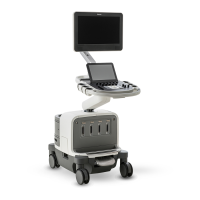
Figure 6-1 Chassis to Ground Resistance Test Diagram
Chassis-to-Ground Resistance Test Procedure
➤ To test the system for resistance between chassis and ground
1. Inspect the power cord for cracks and wear.
2. Set the mode on the analyzer to measure resistance in the power cord.
3. Plug the analyzer into an available AC wall outlet. Plug the ultrasound system power plug into
the test receptacle on the analyzer.
4. Make the appropriate connections between the analyzer and the ground lug on the ultra-
sound system’s I/O panel.
5. Read chassis ground resistance in milliohms. Flex the ultrasound power cord during the test
to detect intermittent changes in resistance value.
Hot -
Neutral -
Ground wire
Green or
R = 200 milliohms maximum
Chassis
R
LIMIT: UL, CSA and IEC:
300e036
Green/Yellow
Power cord disconnected from AC power.
ground
System
under
test
(resistance)