4535 612 10261 HD11 Service Manual Page 289
CSIP Level 1 Cabling: Foldouts
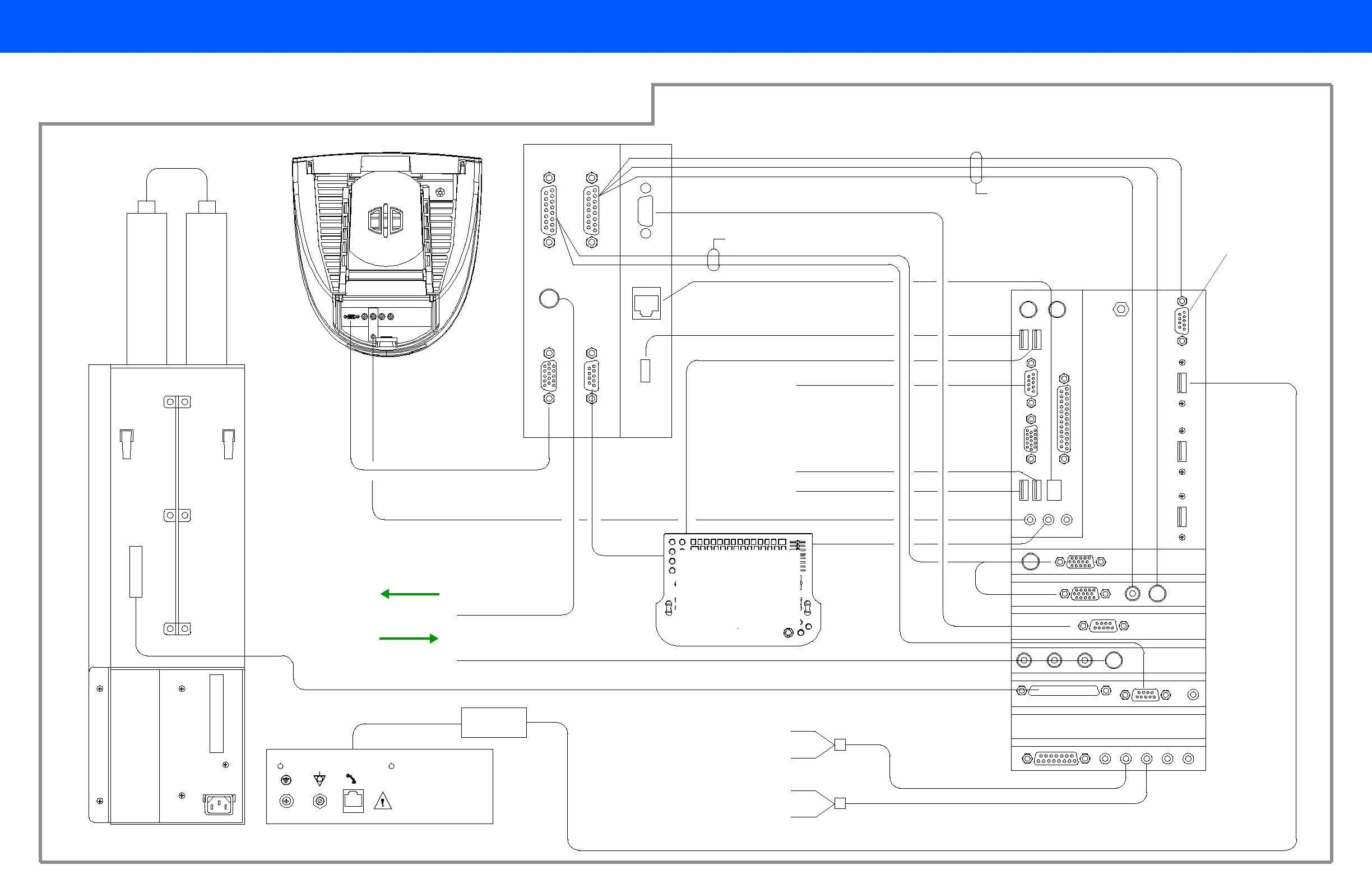
Figure 11-1 HD11 Ultrasound System Signal Interconnect Diagram
Video monitor
E-box
PC
Upper I/O panel (rear view)
(Rear view) Lower I/O panel
20
19
16
16
11
To V C R
2
15
13
18
14
17
21
13
VCR (Video In)
VCR (Video Out)
18
10
3
Modem
Phone cable is part of modem
USB cable is part
of modem
Video I/O A
Signal Distribution PCB
(Inside E-box)
Backplane PCB
(Inside E-box)
8
Power
supply
Video I/O B
To color printer
To B&W printer
See CAUTION
See CAUTION
For PC internal
signal cabling,
See Figure 11-3
VCR Audio In Right (red)
VCR Audio In Left (white)
VCR Audio Out Right (red)
VCR Audio Out Left (white)
To
peripheral
tray
To peripheral tray
Keyboard
Auxiliary power
connector
See CAUTION
5 int or 4 ext
See Figure 11-16
for control panel
cable locations
18
17
14
19
19
19
13
15
2
5 int or 4 ext
10