4535 612 10261 HD11 Service Manual Page 251
CSIP Level 1 Disassembly and Reassembly: Disassembly Procedures
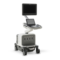
Figure 10-64 Removing the Rear Vent and Faceplate
Cables
Torx screws
(4 plcs)
10
Rear vent
11
12
Rear I/O faceplate
13
14
Splitter can
Torx screws (2 plcs)
Standoff
screws
(2 plcs)
9
9. Pull the modem off the velcro strip
on the side of the splitter can.
10. Remove the four Torx screws secur-
ing the rear vent to the Rear I/O
faceplate.
11. Remove the two standoff screws
securing the serial connector to the
Rear I/O faceplate. Remove the
cable.
12. Remove the two Torx screws secur-
ing the USB connector to the Rear
I/O faceplate. Remove the cable.
13. Disconnect the LAN cable from the
back of the Rear I/O faceplate.
14. Disconnect the five remaining cables
from the back of the Rear I/O split-
ter can. Proceed to step 15.