4535 612 10261 HD11 Service Manual Page 37
CSIP Level 1 General Information: Physical Description
Physical
Description
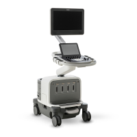
The HD11 physical structure is made of fabricated sheet metal and molded plastic parts. The sys-
tem (Figure 1-1) consists of a cart, a user interface (control panel), a visual display (video moni-
tor), and the ultrasound electronic components. The major ultrasound components are the PC,
the E-box, and the system power supply.
Cart
The cart is made up of a base and framework that provides a chassis on which all system compo-
nents are installed and interconnected.
Swivel-casters at the four corners of the cart base provide system maneuverability and braking.
The front casters can be fixed straight and locked, or unlocked, by foot-operated wheel locks to
mobilize or immobilize the system as needed.
A vertical and horizontal adjustment feature allows physical positioning of the control panel and
monitor. The control panel and the monitor adjust up and down and swivel as a unit. The moni-
tor also independently tilts and swivels on its mount.
Input/output (I/O) panels (upper and lower) installed into the rear of the cart framing provide for
external system connections (see “I/O Panels” on page 73).
System Control
Panel
The control panel (Figure 1-2) is a replaceable, self-contained module. The control panel
physically connects with the imaging system through a USB cable that connects to the internal
PC. The USB cable provides power for the trackball, the Enter and Select keys, and the
QWERTY keyboard. All the other control-panel functions are powered by a cable from the
system power supply.
The system control panel contains a backlit alphanumeric keyboard, slide controls, knobs,
hard-coded and software-driven keys, and a trackball.
The system control panel includes two numbered option keys (Option 1 and Option 2) whose
functions are assigned by the customer. For details on configuring these controls, see the HD11
Help.