4535 612 10261 HD11 Service Manual Page 39
CSIP Level 1 General Information: Physical Description
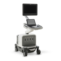
System Monitor
The video monitor (Figure 1-1) is a 15-in color display mounted on a “twivel” assembly. The
twivel allows tilt and swivel positioning of the display for ease of viewing.
PC
Behind the left-side system cover (Figure 1-1), the HD11 uses a commercial personal computer
(PC) tower as a central processor running Microsoft Windows XP Embedded Operating System
software.
This PC houses several electronic components, which include the PC power supply, an E-box
input/output board, a 3-board video circuit, the system hard disk drive (HDD), a CD-RW drive,
and, when installed, the optional magneto-optical disk (MOD) drive.
The optional Physio module installs in one of the PC’s front drive bays.
The VCR option boards reside in the PC PCI slots when installed.
E-box
Behind the right-side system cover (Figure 1-1), is the E-box, a card cage that houses the
ultrasound signal generation and echo acquisition circuits. The E-box shares system framework
that provides mounting for the transducer connector modules. The following ultrasound system
electronic circuits are contained in the E-box:
• A system Motherboard (backplane)
• A Signal Distribution Board
• Four Transmit and Receive (TR) Boards (TR0, TR1, TR2, and TR3)
• A Signal Processor Board
• A Motor Controller Board
System Power
Supply
The system power supply—an enclosed, self-contained, replaceable module—is mounted under
the E-box (Figure 1-1).