4535 612 10261 HD11 Service Manual Page 316
CSIP Level 1 Configuration: Primary PCB Information
Primary PCB
Information
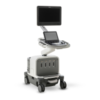
The HD11 primary PCB locations are shown in Figure 13-1 (PC), Figure 13-2 (E-box), and
Figure 13-3 (Rear Upper I/O panel). These PCBs are shown in Figure 13-4 through Figure 13-18.
There are no PCB PROMs or PCB jumpers that are required to be configured in the field.
Table 13-1 Software Part Numbers
989605346091 SW, HD11 System
453561188495 1.0.0 SW, System Application Files, HD11, Virtual
453561188511 OS.03, SW, HD11, Virtual
453561188541 COTS.09, SW, COTS, Virtual
CDs
453561188485 1.0.0, SW, System Application Files, HD11
453561188501 OS.03, SW (2 CDs)
453561188531 COTS.09, SW