RL78/G15 CHAPTER 6 TIMER ARRAY UNIT
R01UH0959EJ0110 Rev.1.10 Page 166 of 765
Mar 7, 2023
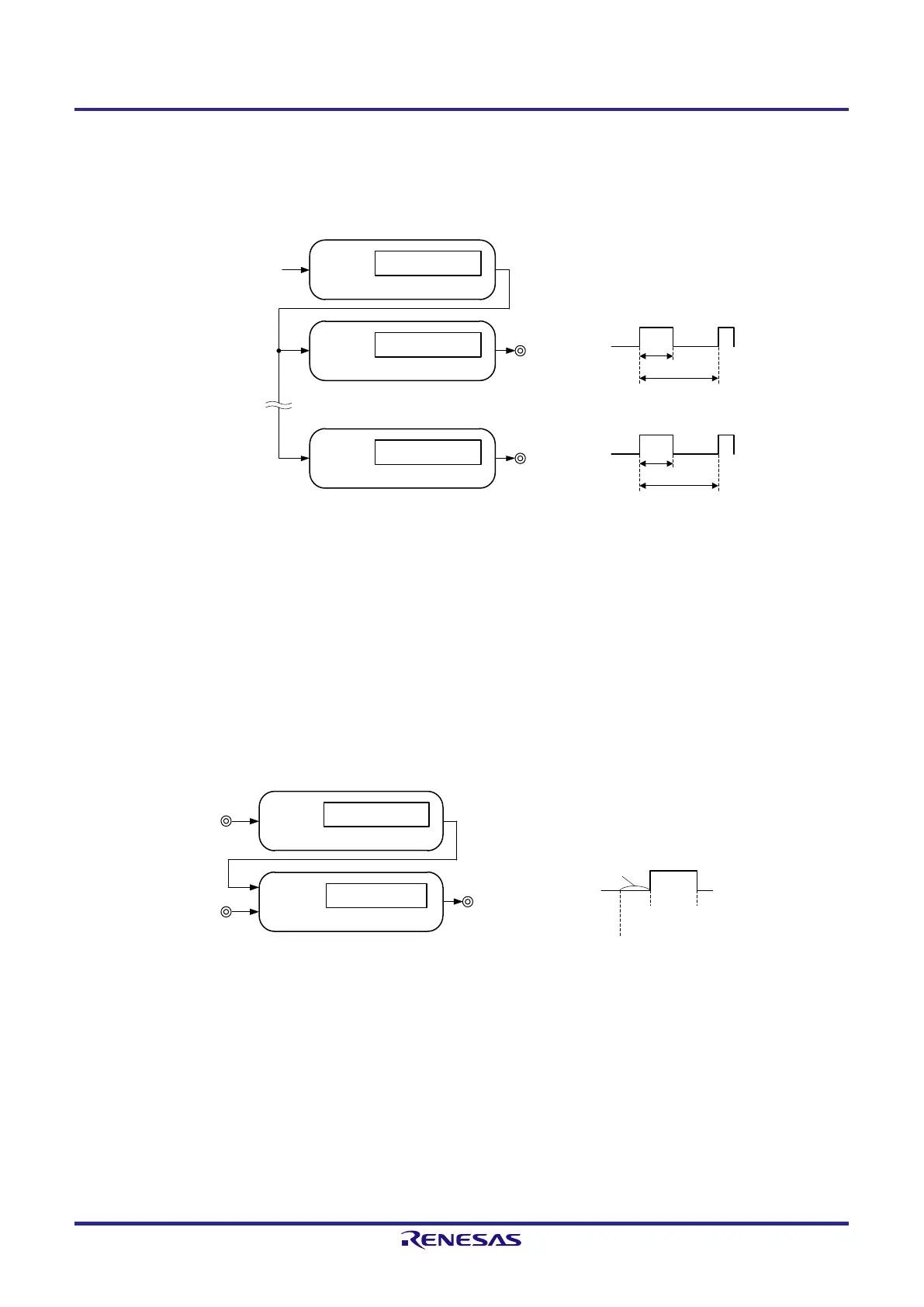
3) Multiple PWM (Pulse Width Modulation) output
By extending the PWM function and using one master channel and two or more slave channels, up to seven types of
PWM signals that have a specific period and a specified duty factor can be generated.
Channel n (master)
Interrupt signal
(INTTMmn
)
Compare operation
Channel p (slave)
Timer output
(TOmp)
Compare operation
Operation clock
Duty
Period
Channel q (slave)
Timer output
(TOmq)
Compare operation
Duty
Period
•
•
•
•
Caution For details about the rules of simultaneous channel operation function, see 6.4.1 Basic rules of
simultaneous channel operation function.
Remark m: Unit number (m = 0), n: Channel number (n = 0 to 7)
p, q: Slave channel number (n < p < q ≤ 7)
4) Two-channel input with one-shot pulse output function
Two channels are used as a set to generate any one-shot pulse by setting or resetting the timer output pin (TO03) at a
valid edge of the timer input pin (TI0n, TI03) input.
Channel n (master)
Interrupt request signal
(INTTM0n)
Compare operation
Timer input
(TI0n)
Channel 3 (slave)
Timer output
(TO03)
Capture operation
Set
(INTTM0n)
Output
timing
Start
(TI0n edge detection)
Reset
(TI03 edge detection)
Timer input
(TI03)
Caution There are several rules for using the simultaneous channel operation function.
For details, see 6.4.1 Basic rules of simultaneous channel operation function.
Remark n: Channel number (n = 0, 2)
p: Slave channel number (p = 3)
 Loading...


