RL78/G15 CHAPTER 6 TIMER ARRAY UNIT
R01UH0959EJ0110 Rev.1.10 Page 169 of 765
Mar 7, 2023
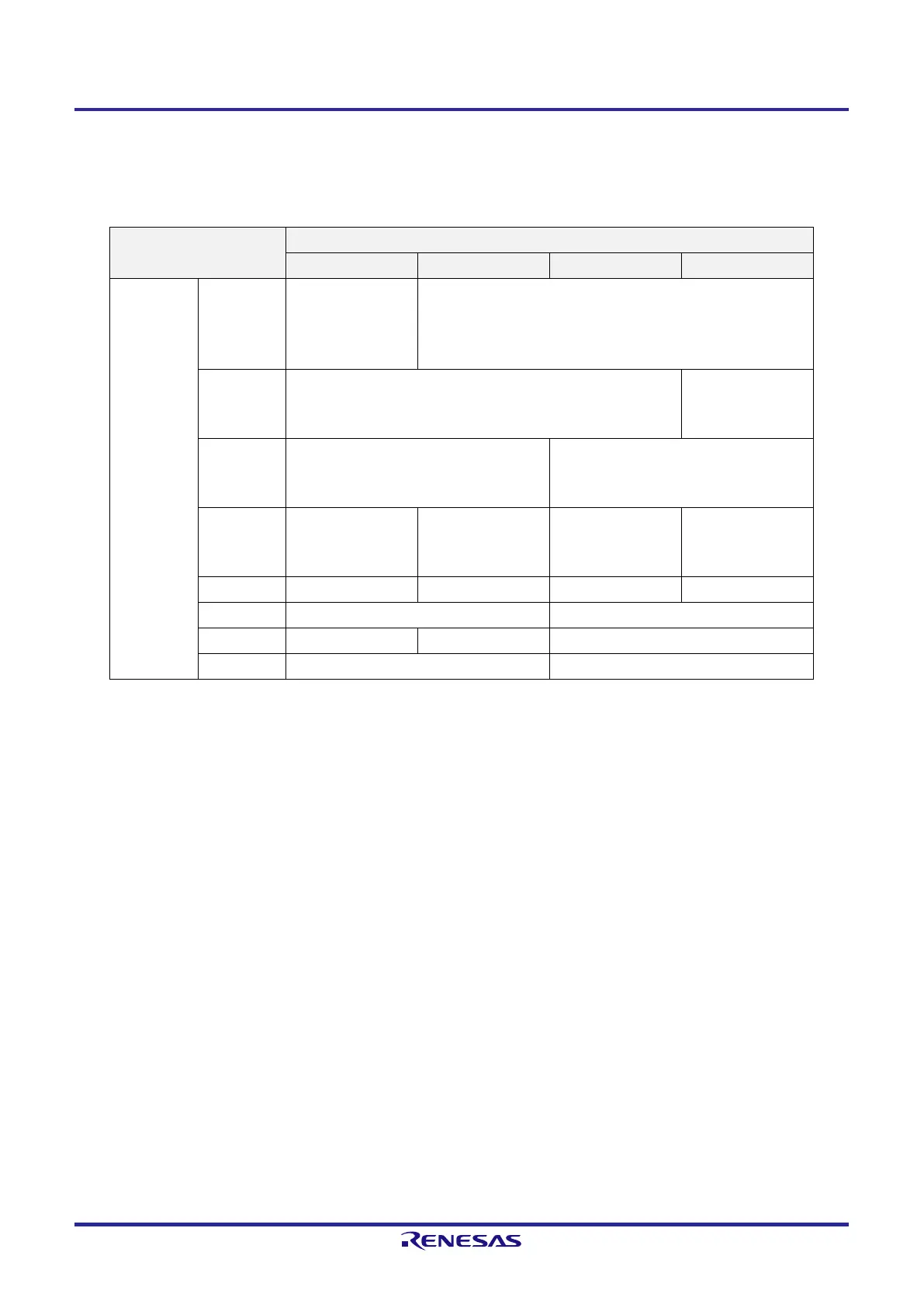
The presence or absence of timer I/O pins in each timer array unit channel depends on the product.
Table 6-2. Timer I/O Pins provided in Each Product
Timer array unit channels I/O Pins of Each Product
20-pin 16-pin 10-pin 8-pin
Unit 0 Channel 0 P21/(TO00)
P20/(TI00)
P137/TI00
P03/TO00/(TI00)
P137/TI00
P03/TO00/(TI00)
Channel 1 P40/(TI01/TO01)
P02/(TI01/TO01)
P04/TI01/TO01
P40/(TI01/TO01)
P04/TI01/TO01
Channel 2 P41/(TI02/TO02)
P01/(TI02/TO02)
P05/TI02/TO02
P01/TI02/TO02
Channel 3 P41/TI03/TO03
P07/(TO03)
P20/(TI03/TO03)
P41/TI03/TO03
P07/(TO03)
— —
Channel 4 P23/TI04/TO04 — — —
Channel 5 P122/TI05/TO05 —
Channel 6 P22/TI06/TO06 — —
Channel 7 P121/TI07/TO07 —
Remark 1. When timer input and timer output are shared by the same pin, either only timer input or only timer output
can be used.
Remark 2. —: There is no timer I/O pin, but the channel is available. (However, the channel can only be used as an
interval timer.)
×: The channel is not available.
Remark 3. Pins in the parentheses indicate an alternate port when setting the peripheral I/O redirection register 0 to 3
(PIOR0 to PIOR3). For details, see 4.3.6 Peripheral I/O redirection registers 0 to 3 (PIOR0 to PIOR3).
 Loading...


