RL78/G15 CHAPTER 6 TIMER ARRAY UNIT
R01UH0959EJ0110 Rev.1.10 Page 228 of 765
Mar 7, 2023
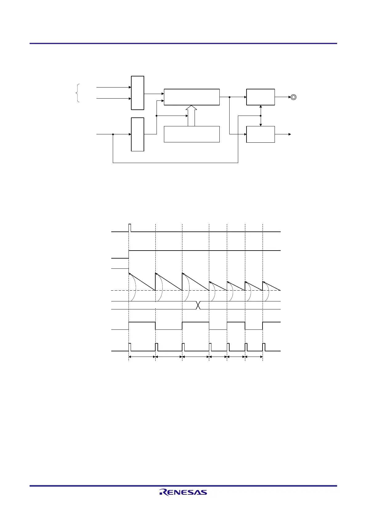
Figure 6-40. Block Diagram of Operation as Interval Timer/Square Wave Output
TOmn pin
Interrupt signal
(INTTMmn)
Timer data register mn
(TDRmn)
Output
controller
TSmn
CKm0
CKm1
Timer counter register mn
(TCRmn)
Interrupt
controller
Operation clock
Note 1
Clock selection
Trigger
selection
Note 1. When channels 1 and 3, the clock can be selected from CKm0, CKm1, CKm2 and CKm3.
Figure 6-41. Example of Basic Timing of Operation as Interval Timer/Square Wave Output (MDmn0 = 1)
TSmn
TEmn
TDRmn
TCRmn
TOmn
INTTMmn
a
a + 1
b
a + 1 a + 1 b + 1
0000H
b + 1 b + 1
Remark 1. m: Unit number (m = 0), n: Channel number (n = 0 to 7)
Remark 2. TSmn: Bit n of timer channel start register m (TSm)
TEmn: Bit n of timer channel enable status register m (TEm)
TCRmn: Timer count register mn (TCRmn)
TDRmn: Timer data register mn (TDRmn)
TOmn: TOmn pin output signal
 Loading...


