RL78/G15 CHAPTER 6 TIMER ARRAY UNIT
R01UH0959EJ0110 Rev.1.10 Page 246 of 765
Mar 7, 2023
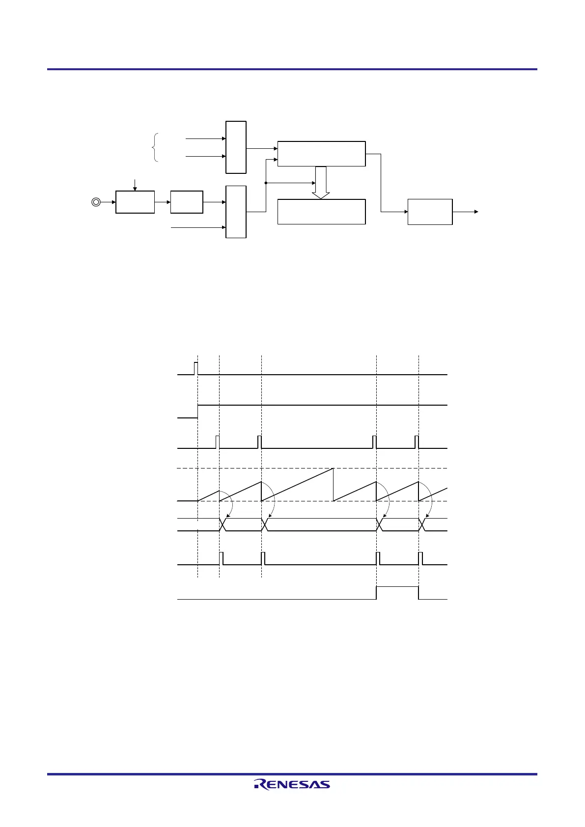
Figure 6-52. Block Diagram of Operation as Input Pulse Interval Measurement
Interrupt signal
(INTTMmn)
Timer data register mn
(TDRmn)
TSmn
TImn pin
Timer counter register mn
(TCRmn)
Interrupt
controller
Edge
detection
Noise filter
TNFENmn
CKm0
CKm1
Operation clock
Note 1
Clock selection
Trigger
selection
Note 1. When channels 1 and 3, the clock can be selected from CKm0, CKm1, CKm2 and CKm3.
Remark m: Unit number (m = 0), n: Channel number (n = 0 to 7)
Figure 6-53. Example of Basic Timing of Operation as Input Pulse Interval Measurement (MDmn0 = 0)
TSmn
TEmn
TDRmn
TCRmn
INTTMmn
OVF
0000H
TImn
FFFFH
a
b
c
d
a
b c d
0000H
Remark 1. m: Unit number (m = 0), n: Channel number (n = 0 to 7)
Remark 2. TSmn: Bit n of timer channel start register m (TSm)
TEmn: Bit n of timer channel enable status register m (TEm)
TImn: TImn pin input signal
TCRmn: Timer count register mn (TCRmn)
TDRmn: Timer data register mn (TDRmn)
OVF: Bit 0 of timer status register mn (TSRmn)
 Loading...


