RL78/G15 CHAPTER 12 SERIAL ARRAY UNIT
R01UH0959EJ0110 Rev.1.10 Page 438 of 765
Mar 7, 2023
(1) Register setting
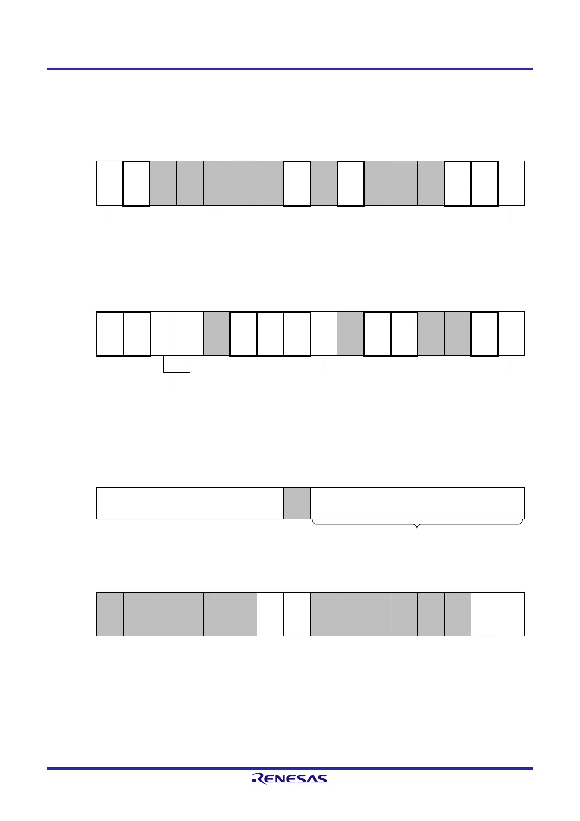
Figure 12-53. Example of Contents of Registers for Slave Reception of simplified SPI (CSI00, CSI01) (1/2)
(a) Serial mode register mn (SMRmn)
15 14 13 12 11 10 9 8 7 6 5 4 3 2 1 0
SMRmn
CKSm
n
CCSm
n
STSm
n
SISmn
0
MDmn
2
MDmn
1
MDmn
0
0/1 1 0 0 0 0 0 0 0 0 1 0 0 0 0 0
Operation clock (f
MCK
) of channel n
0: Prescaler output clock CKm0 set by the SPSm register
1: Prescaler output clock CKm1 set by the SPSm register
Interrupt source of channel n
0: Transfer end interrupt
(b) Serial communication operation setting register mn (SCRmn)
15 14 13 12 11 10 9 8 7 6 5 4 3 2 1 0
SCRmn
TXEm
n
RXEm
n
DAPm
n
CKPm
n
EOCm
n
PTCm
n1
PTCm
n0
DIRmn
SLCm
n1
SLCm
n0
DLSm
n1
DLSm
n0
0 1 0/1 0/1 0 0 0 0 0/1 0 0 0 0 1 1 0/1
Selection of data transfer sequence
0: Inputs/outputs data with MSB first
1: Inputs/outputs data with LSB first
Setting of data length
0: 7-bit data length
1: 8-bit data length
Selection of the data and clock phase
(For details about the setting, see 12.3
Registers to Control the Serial Array
Unit.)
(c) Serial data register mn (SDRmn) (lower 8 bits: SIOp)
15 14 13 12 11 10 9 8 7 6 5 4 3 2 1 0
SDRmn 0000000
Baud rate setting
Receive data
0
SIOp
(d) Serial output register m (SOm) … This register is not used in this mode.
15 14 13 12 11 10 9 8 7 6 5 4 3 2 1 0
SOm
CKOm
1
CKOm
0
SOm1
SOm0
0 0 0 0 0 0 × × 0 0 0 0 0 0 × ×
(Remarks are listed on the next page.)
 Loading...


