No
Release serial interface IICA0 from the reset state and
start clock supply.
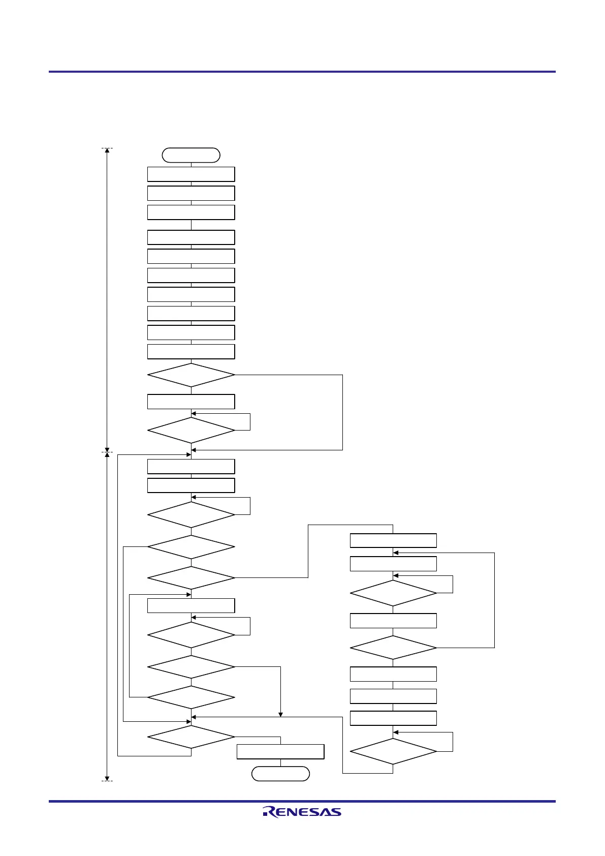
START
Set the PER
0
register
Initialize the I
2
C bus
Note 1
Set the port
IICWL0, IICWH0 ←
xxH
SVA
0 ← xxH
IICF0 ← 0xH
Set STCEN0, IICRSV0 = 0
Set IICCTL01
IICCTL
00 ←
0
xx
111xxB
ACKE0 = WTIM0 = SPIE0
= 1
IICCTL00
←
1
xx111
xxB
IICE0
= 1
Set the port
STCEN0 = 1
?
SPT
0 = 1
INTIICA0
interrupt occurred?
STT
0
= 1
Write to IICA0
INTIICA0
interrupt occurred?
ACKD0 =
1?
TRC0 = 1?
Write to IICA0
INTIICA0
interrupt occurred?
ACKD0 = 1?
End of transfer?
Restart?
Setting of the port multiplexed with the pin to be used
First
, set the port to input mode and the output latch to 0
(
see
13.
3
.8
Registers controlling port functions of IICA serial input/output pins).
Set the transfer clock
Set the local address
Sets the start condition
Set the port from input mode to output mode and enable the output of the I
2
C bus
(see 13.3.8 Registers controlling port functions of IICA serial input/output pins).
Yes
Prepare for starting communication
(generate a stop condition)
No
Wait for detection of the stop
condition
Yes
Prepare for starting communication
(generate a start condition)
Start communication
(specify the address and transfer direction)
No
Wait for detection of ACK
Yes
Yes
No
Yes
Start transmission
No
Wait for data transmission
Yes
Yes
SPT0 = 1
END
No
Yes
Yes
No
INTIICA0
interrupt occurred?
WREL0 = 1
ACKE0 = 0
WTIM0 = 1
Yes
End of transfer?
Yes
Read IICA0
INTIICA0
interrupt occurred?
Yes
No
No
No
No
WREL0 = 1
ACKE0 =
1
WTIM0 =
0
Wait for data
reception
Start reception
Communication processing Initial settings
Wait for detection of ACK
No
(Note 1 and Remark are listed on the next page.)
 Loading...


