RL78/G15 CHAPTER 14 INTERRUPT FUNCTIONS
R01UH0959EJ0110 Rev.1.10 Page 602 of 765
Mar 7, 2023
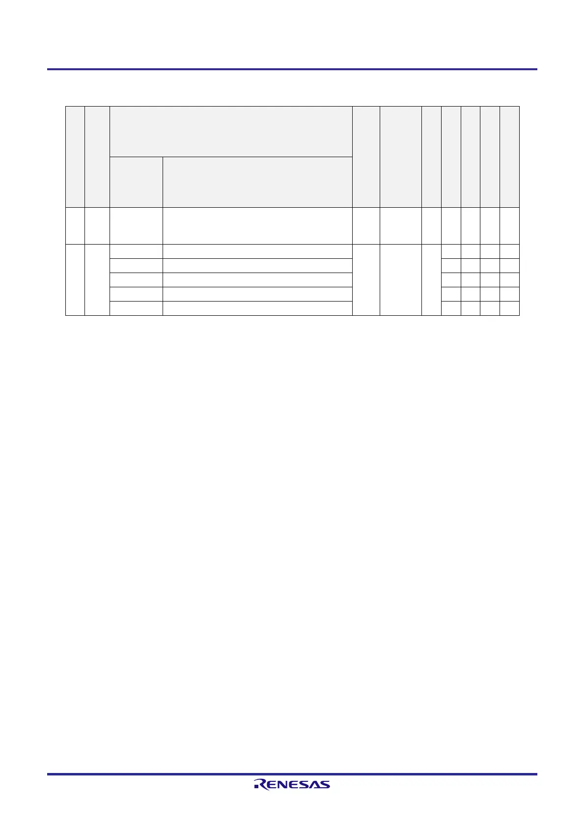
Table 14-1. Interrupt Source List (2/2)
interrupt Type
Default Priority
Note 1
Interrupt Source
Internal/External
Vector Table Address
Basic Configuration Type
Note 2
20-pin
16-pin
10-pin
8-pin
Name Trigger
Software
— BRK Execution of BRK instruction — 0007EH (C)
Reset
— RESET RESET
pin input — 00000H —
SPOR Selectable power-on-reset
WDT Overflow of watchdog timer
TRAP Execution of illegal instruction
Note 3
IAW Illegal memory access
Note 1. The default priority determines the sequence of interrupts if two or more maskable interrupts occur
simultaneously. 0 indicates the highest priority and 26 indicates the lowest priority.
Note 2. Basic configuration types (A) to (C) correspond to (A) to (C) in Figure 14-1.
Note 3. A reset is generated when the instruction code in FFH is executed.
No reset is generated if an illegal instruction is executed during emulation by the on-chip debug emulator.
Note 4. Completion of counting by a channel of the array unit is only possible.
 Loading...


