RL78/G15 CHAPTER 15 STANDBY FUNCTION
R01UH0959EJ0110 Rev.1.10 Page 628 of 765
Mar 7, 2023
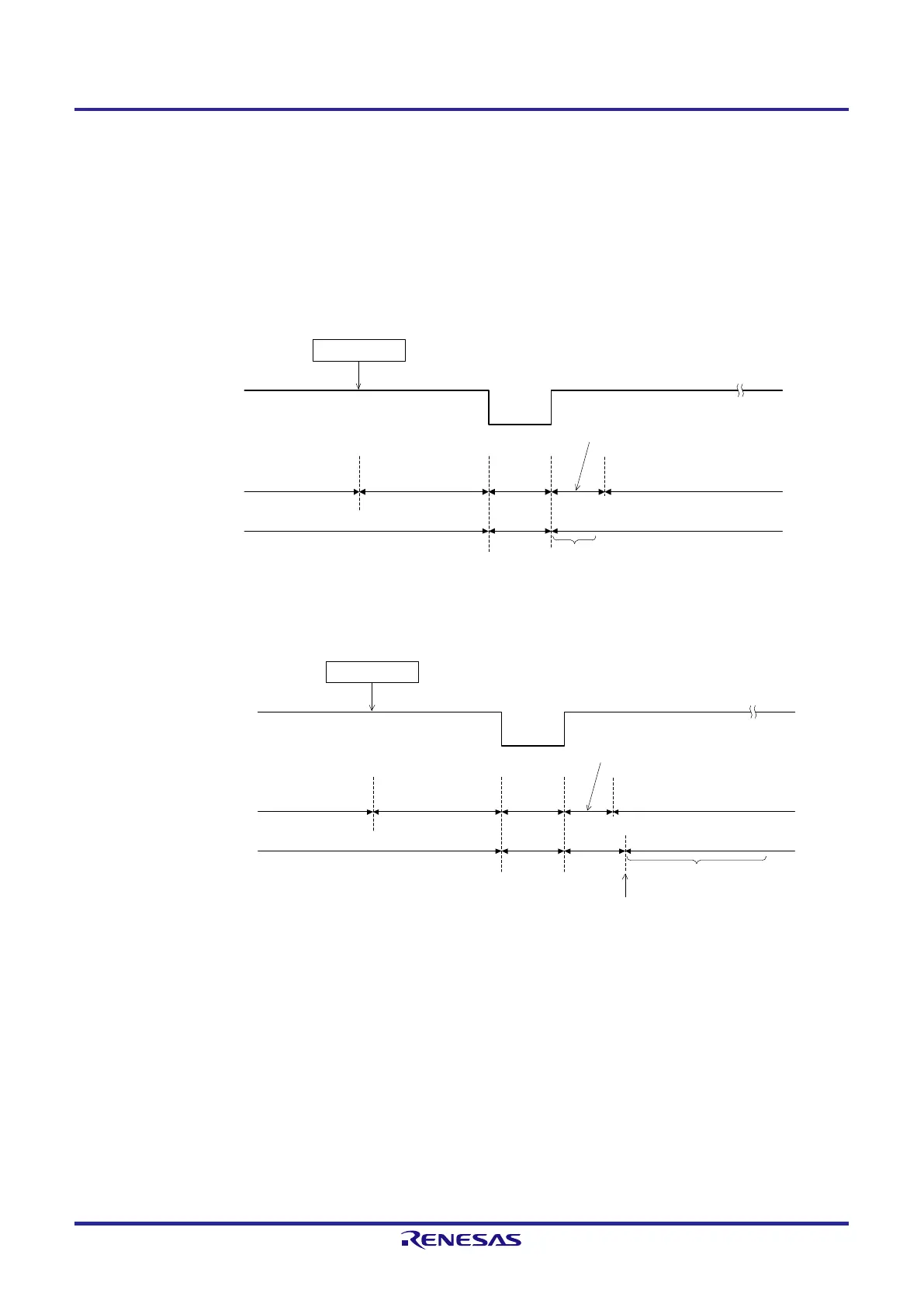
b) HALT mode release by reset signal generation
When the reset signal is generated, HALT mode is released, and then, as in the case with a normal reset operation,
the program is executed after branching to the reset vector address.
Figure 15-2. HALT Mode Release by Reset Signal Generation
(1) When high-speed on-chip oscillator clock is used as CPU clock
__________
Reset signal
Reset period
Oscillation
stopped
Oscillates
Reset processing
Note 1
Wait for oscillation
accuracy stabilization
Status of CPU
High-speed on
-chip
oscillator clock
Normal operation
(high-speed on-chip
oscillator clock)
HALT mode
Oscillates
Normal operation
(high-speed on-chip oscillator clock)
HALT instruction
(2) When high-speed system clock is used as CPU clock (16-pin and 20-pin products only)
__________
Reset signal
Reset period
Oscillation
stopped
Oscillates
Oscillation stabilization time
(check by using OSTC register)
Status of CPU
High-speed system clock
(X1 oscillation)
Normal operation
(high
-speed system clock)
HALT mode
Oscillates
Normal operation
(high-speed on-chip oscillator clock)
Starting X1 oscillation is
specified by software
.
Oscillation
stopped
Reset processing
Note 1
HALT instruction
Note 1. For the reset processing time, see CHAPTER 16 RESET FUNCTION. For the reset processing time of the
SPOR circuit, see CHAPTER 17 SELECTABLE POWER-ON-RESET CIRCUIT.
 Loading...


