12.1.4 Parameter set selection
This function allows to switch between two sets of parameters. It is used if the
motors are switched at the output of the frequency converter and two motors
should be driven by one device.
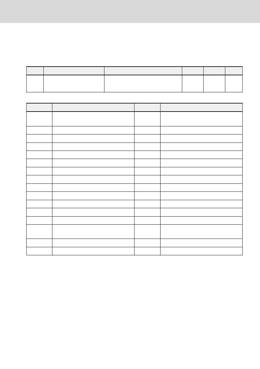
Code Name Setting range Default Min. Attri.
b0.12 Parameter set selection
0: Parameter set 1 active
1: Parameter set 2 active
0 – Stop
Following parameters are inside the switchable parameter set:
Code Name Code Name
C1.05 Motor rated power C1.74
Motor thermal model protection time
constant
C1.06 Motor rated voltage C1.75 Low speed derating frequency
C1.07 Motor rated current C1.76 Zero speed load
C1.08 Motor rated frequency C2.00 V/f curve mode
C1.09 Motor rated speed C2.01 V/f frequency 1
C1.10 Motor rated power factor C2.02 V/f voltage 1
C1.11 Motor poles C2.03 V/f frequency 2
C1.12 Motor rated slip frequency C2.04 V/f voltage 2
C1.20 Motor no-load current C2.05 V/f frequency 3
C1.21 Stator resistance C2.06 V/f voltage 3
C1.22 Rotor resistance C2.07 Slip compensation factor
C1.23 Leakage inductance C2.21 Torque boost setting
C1.24 Mutual inductance C2.22 Automatic torque boost factor
C1.69
Motor thermal model protection set-
ting
E0.00 First frequency setting source
C1.70 Motor overload pre-warning level E0.01 First run command source
C1.71 Motor overload pre-warning delay
Parameter set switch can be carried out in 2 different ways:
● By parameter b0.12:
When the value is changed the parameter set according to the parameter will
be loaded. A parameter set switch can only be carried out in STOP mode. Dur-
ing power up parameter set is loaded according to setting of b0.12, if none of
the digital inputs is used to switch between the parameters sets.
EFC x610 Series
Bosch Rexroth AG
Functions and Parameters
DOK-RCON03-EFC-X610***-IT05-EN-P
103/389

 Loading...


