8.2.2 Control Cables
The following requirements are applicable to the signal connection wiring:
● Flexible cables with wire end sleeves
● Cable cross-section: 0.2...1.0 mm
2
● Cable cross-section for connectors with insulation sleeves: 0.25...1.0 mm
2
● Analog inputs AI1, AI2, EAI, +10 V, +5 V and GND: use shielded cables
● Digital inputs X1...X5, EX1...EX4, SC, +24 V and COM: use shielded cables
● Analog outputs AO1, EAO and GND: use shielded cables
● RS485 communication: use shielded twisted pair cables
EAI, EX1...EX4 and EAO belong to I/O card.
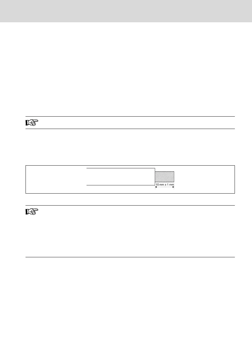
Recommendations on cable insulation stripping:
Please strip the insulation of control cables according to the dimensions given
below. Too long stripping may cause short circuit of adjacent cables; too short
stripping may lead to cables becoming loose.
Fig. 8-3: Cable insulation stripping length
Please follow the steps below for wiring of control terminals.
Step 1: Switch off the frequency converter before performing wiring.
Step 2: Deactivate the control signals in the wiring process.
Step 3: Switch on the frequency converter.
Step 4: Set respective parameters.
Step 5: Activate respective control signals.
EFC x610 Series Bosch Rexroth AG
Frequency Converter Wiring
DOK-RCON03-EFC-X610***-IT05-EN-P
47/389
 Loading...


