Home
REXROTH
DC Drives
EFC 3610 Series
Page 67 (Figures and Dimensions)
REXROTH EFC 3610 Series - Figures and Dimensions; Figures
422 pages
Manual
Save Page as PDF
To Next Page
To Next Page
To Previous Page
To Previous Page
Loading...
7.4
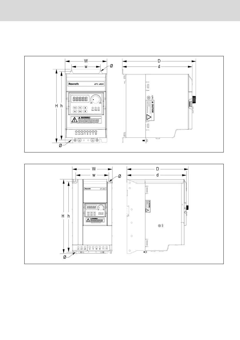
Figures and Dimensions
7.4.1
Figur
es
Fig. 7-2:
EFC x610 0K40...4K00 dimensions figure
Fig. 7-3:
EFC x610 5K50...22K0 dimensions figure
EFC x610 Series
Bosc
h Rexrot
h AG
F
requency Conv
er
ter Mounting
DOK-RCON03-EFC-X610***-IT05-EN-P
35/
389
66
68
Table of Contents
Main Page
Table of Contents
19
Safety Instructions for Electric Drives and Controls
33
Definitions of Terms
33
Explanation of Signal Words and the Safety Alert Symbol
35
General Information
36
Using the Safety Instructions and Passing Them on to Others
36
Requirements for Safe Use
36
Hazards by Improper Use
38
Instructions with Regard to Specific Dangers
39
Protection against Contact with Electrical Parts and Housings
39
Protective Extra-Low Voltage as Protection against Electric Shock
40
Protection against Dangerous Movements
40
Protection against Magnetic and Electromagnetic Fields During Operation and Mounting
42
Protection against Contact with Hot Parts
43
Protection During Handling and Mounting
43
Important Directions for Use
44
Appropriate Use
44
Inappropriate Use
44
Documentation Information
45
About this Documentation
45
Reference
45
Delivery and Storage
46
Product Identification
46
Packing Nameplate
46
Product Nameplate
47
Visual Inspection
48
Scope of Supply
48
Transport of the Components
49
Storage of the Components
49
Drive System Overview
50
Input
51
Output
51
V/F Control Performance
51
SVC Control Performance
51
Frequency Converter Overview
51
Product Features
51
Main Functions
52
Communication
53
Operating Panel
53
Protection
53
Conditions
54
Technical Data
55
Electric Data
55
Derating of Electric Data
57
Derating and Ambient Temperature
57
Derating and Mains Voltage
58
Derating and Carrier Frequency
59
Maximum Length of Motor Cables
62
Frequency Converter Mounting
63
Installation Conditions
63
Heat Dissipation
64
Air Flow of Fans
65
Figures and Dimensions
67
Figures
67
Dimensions
70
DIN Rail Mounting
72
Frequency Converter Wiring
73
Wiring Diagram
73
Cable Specifications
74
Power Cables
74
Cable Specification for International Without USA / Canada
74
Cable Specification for USA / Canada
76
Dimensioning Variables of the Table Values
77
Control Cables
79
Terminals
80
Power Terminals
80
Power Terminals Description
80
Power Terminals Figure
80
Notes on DC-Bus Terminals
81
Control Terminals
86
Control Terminals Figure
86
Control Terminals Description
87
Digital Outputs
88
Analog Outputs
88
External Power Supply
88
Digital Input NPN / PNP Wiring
89
Digital Output Do1A, Do1B Load Pull-Up / Pull-Down Wiring
90
Analog Input Terminals (AI1, AI2, EAI, +10 V, +5 V, Earth and GND)
91
Relay Output Terminals
92
Notes on DC_IN Terminal
93
Electromagnetic Compatibility (EMC)
95
EMC Requirements
95
General Information
95
The Electromagnetic Compatibility (EMC) or Electromagnetic Interference (EMI) Includes the Following Requirements
95
Noise Immunity in the Drive System
95
Basic Structure for Noise Immunity
95
Minimum Immunity Requirements for Pdss Intended for Use in the Second Environment
96
Minimum Immunity Requirements for Pdss Intended for Use in the First Environment
97
Evaluation Criterion
98
Noise Emission of the Drive System
99
Ensuring the EMC Requirements
104
EMC Measures for Design and Installation
106
Rules for Design of Installations with Drive Controllers in Compli- Ance with EMC
106
EMC-Optimal Installation in Facility and Control Cabinet
108
Control Cabinet Mounting According to Interference Areas - Exem- Plary Arrangements
110
Design and Installation in Area a - Interference-Free Area of Control Cabinet
111
Design and Installation in Area B - Interference-Susceptible Area of Control Cabinet
114
Design and Installation in Area C - Strongly Interference-Susceptible Area of Control Cabinet
115
Ground Connections
116
Installing Signal Lines and Signal Cables
117
General Measures of Radio Interference Suppression for Relays, Contactors, Switches, Chokes and Inductive Loads
118
Operating Panel and Dust Cover
119
LED Panel
119
LED Display
119
Dust Cover
120
LED Indicator
121
Operating Descriptions
122
Fast Access to Parameters with Button Combinations
123
Digit Shifting Function for Modification of Parameter Values
124
Quick Start
125
Checklist before Quick Start
125
Step 1: Check Application Conditions
125
Step 2: Check Mounting Conditions
125
Step 3: Check the Wiring
125
Quick Start Parameters
126
Control the Motor
127
Motor Parameters Auto-Tuning
128
Possible Errors During Quick Start and Respective Solutions
129
Restoring Parameters to Factory Defaults
129
Functions and Parameters
130
Basic Settings
130
Parameter Group Access Control
130
Parameter Initialization
132
Parameter Replication
133
Parameter Set Selection
135
Password Protection
137
Input and Output Terminals Configuration
138
Digital Input Configuration
138
X5 Pulse Input Configuration
140
Analog Input Configuration
142
Digital Output Configuration
143
Analog Output Configuration
145
I/O Card Terminal Configuration
147
Set Digital Input Terminals
147
Set Analog Input Terminals
148
Set Digital / Analog Output Terminals
152
Perform the Self-Test Function
152
Relay Card Terminal Configuration
154
Set the Relay Terminals
154
Perform the Self-Test Function
155
Power Stage Configuration
156
Set the Control Mode
156
Normal / Heavy Duty Setting
156
Carrier Frequency Setting
157
Fan Control
158
Fan Maintenance Reminder
159
Basic Frequency Setting Sources
160
Function Description
160
Select the Frequency Setting Source
161
General Setting
161
Frequency Setting Source Switching
162
Frequency Setting Sources Combination
163
Adjust the Setting Frequency by Panel Potentiometer
164
Adjust the Setting Frequency by Panel Button
164
Adjust the Setting Frequency by Analog Inputs
165
Adjust the Setting Frequency by X5 Pulse Input
165
Adjust the Setting Frequency by Digital Input up / down Command
166
Adjust the Setting Frequency by Multi-Speed Function
168
Acceleration and Deceleration Configuration
174
Acceleration and Deceleration Time Configuration
174
Acceleration and Deceleration Curve Mode Configuration
175
Output Frequency Limitation
178
Direct Output Frequency Limitation
178
Behavior at Low Speed Running
178
Frequency Setting Saving
180
Run- / Stop- / Direction Command Source
181
Function Description
181
Run Command Source
182
First and Second Run Command Source Configuration
182
Switch between First and Second Run Command Source
182
Stop Command Via Panel <Stop> Button
183
Direction Control
184
Direction Control Via Operation Panel
184
Reverse Running Frequency
184
Direction Change Dead Time
185
Start Behavior Setting
186
Start Mode Selection
186
Start Directly
186
DC-Braking before Start
187
Start with Speed Capture
188
Automatic Start / Stop According to Setting Frequency
189
Stop Behavior Setting
191
Stop Mode Setting
191
DC-Braking During Deceleration to Stop
192
Overexcitation Braking
193
Resistor Braking
194
Special Running Behaviors
196
Skip Frequency
196
Jog Function
198
2-Wire / 3-Wire Control (Forward / Stop, Reverse / Stop)
200
2-Wire Control Mode 1
200
2-Wire Control Mode 2 (Forward / Reverse, Run / Stop)
201
3-Wire Control Mode 1
202
3-Wire Control Mode 2
203
Run / Stop
203
Special Functions
204
Counter Function
204
Frequency Arrival
207
Frequency Level Detection
209
High Resolution Current Display
210
Simple PLC
211
Function Description
211
Set the Simple PLC Mode
212
Set Speed / Direction / Acceleration and Deceleration Time
213
Stop and Pause Simple PLC Control
215
Indication of Simple PLC Status
216
PID Control
218
Function Description
218
Selecting the Reference and Feedback
219
Control Loop Configuration
221
PID Regulation Mode Setting
222
PID Feedforward Control
223
PID Deactivation by Digital Input
224
PID Engineering Value Display
225
PID Status Indication
226
Sleep / Wake Function
227
Pump Protection Function
229
Protection Functions
231
Converter Protection
231
Overload Pre-Warning
231
Stall Overvoltage Prevention
232
Stall Overcurrent Prevention
233
Phase Loss Protection
235
Analog Input Broken Wire Detection
235
Reaction to External Error Signals
236
Power Fault Ride-Through Setting
237
Motor Protection
238
Motor Derating Frequency at Low Speed
238
Motor Thermal Protection Without Temperature Sensor
239
Motor Overload Pre-Warning
239
Motor Thermal Protection with Temperature Sensor
240
Asynchronous Motor(ASM) Control
243
Motor Parameterization
243
Nameplate Parameters Configuration
243
Motor Slip Frequency Configuration
243
Motor Parameter Auto-Tuning
244
V/F Control
248
V/F Curve Selection
248
User-Defined V/F Curve Configuration
249
Slip Compensation Factor Configuration
251
Torque Boost Setting
252
Optimization Functions for V/F Control
255
SVC Control (EFC 5610 ONLY)
257
SVC Control Loop Configuration
257
Speed Control Mode
257
Torque Control Mode
258
Permanent Magnetized Synchronous Motor (PMSM) Control (Appli- Cable for EFC 5610 Model)
262
The Setting of Motor Type
262
The Setting of Motor Parameter
262
The Nameplate Parameter
262
Auto-Tuning of Motor Parameters
262
PMSM SVC Control
265
SVC Control Loop Configuration
265
Torque Limit in Speed Control Mode
265
Initial Position Checking
265
ASF Function
267
Function Description
267
ASF Parameter
267
ASF Management
269
Download ASF
269
Certify ASF
270
Erase ASF
270
ASF Diagnosis
271
ASF System Error
271
ASF Warning and Error
271
Diagnosis
272
Display of LED Characters
272
Status Code
272
Warning Code
272
Error Code
274
Error 1 (OC-1): Overcurrent at Constant Speed
274
Error 2 (OC-2): Overcurrent During Acceleration
274
Error 3 (OC-3): Overcurrent During Deceleration
274
Error 4 (OE-1): Overvoltage at Constant Speed
275
Error 5 (OE-2): Overvoltage During Acceleration
275
Error 6 (OE-3): Overvoltage During Deceleration
275
Error 7 (OE-4): Overvoltage During Stop
276
Error 8 (UE-1): Undervoltage During Run
276
Error 9 (SC): Surge Current or Short Circuit
276
Error 10 (IPH.L): Input Phase Loss
276
Error 11 (OPH.L): Output Phase Loss
276
Error 12 (ESS-): Soft Start Error
277
Error 20 (OL -1): Converter Overload
277
Error 21 (OH): Converter over Temperature
277
Error 30 (OL -2): Motor Overload
278
Error 22 (UH): Converter under Temperature
278
Error 23 (FF): Fan Failure
278
Error 24 (Pdr): Pump Dry
278
Error 25 (Col -): Command Value Lost
278
Error 31 (Ot): Motor over Temperature
279
Error 32 (T-Er): Motor Parameter Tuning Error
279
Error 33 (Ade-): Synchronous Motor Angle Detection Error
279
Error 38 (Aibe): Analog Input Broken Wire Detection
279
Error 39 (EPS-): DC_IN Power Supply Error
279
Error 40 (Dir1): Forward Running Lock Error
280
Error 41 (Dir2): Reverse Running Lock Error
280
Error 42 (E-St): Terminal Error Signal
280
Error 43 (FFE-): Firmware Version Mismatch
280
Error 44 (Rs-): Modbus Communication Error
280
Error 45 (E.par): Parameter Settings Invalid
281
Error 46 (U.par): Unknown Parameter Restore Error
281
Error 48 (Ida-): Internal Communication Error
281
Error 49 (Idp-): Internal Parameter Error
281
Error 50 (Ide-): Converter Internal Error
281
Error 51 (Ocd-): Extension Card Internal Error
281
Error 52 (Occ): Extension Card Pdos Configuration Error
281
Error 53 (Fdi-): no Valid Process Data
282
Error 54 (Pce-): Remote Control Communication Error
282
Error 55 (Pbre): Parameter Backup / Restore Error
282
Error 56 (Pref): Parameter Restore Error after Firmware Update
282
Error 60 (ASF-): Application Firmware Error
282
Error 61
282
Error Handling
283
Restarting after Power Loss
283
Automatic Error Reset
284
Error Reset by Digital Input
285
Communication
286
Brief Introduction
286
Basic Communication Settings
286
Selection of the Communication Protocol
286
Setting the Data Transmission Rate
286
Setting the Data Format
287
Setting the Local Address
287
Setting Command Signal Type
287
Communication Disruption and Response
288
Modbus Protocol
289
Protocol Description
289
Brief Introduction
289
Transmission
290
Modbus Interface
291
Modbus Function and Message Format
291
Supported Functions
291
Function Example
293
Function 0X06: Write One Register Word
294
Function 0X08: Diagnostics
295
Function 0X10: Write N Register Words, Range: 1
296
Function 0X17: Read/Write N Register Words, Range: 1
296
Error Code and Exception Code
298
Communication Mapping Register Address Distribution
299
Frequency Converter Parameter Address
299
Frequency Converter Register Address
299
Communication Control Register (0X7F00)
300
Communication State Register (0X7Fa0)
301
Additional Status Register (0X7Fa1)
302
Fault Status Register (0X7Fb0)
303
Communication Frequency Setting Register (0X7F01)
303
Modbus Communication Example
304
Special Notes
305
Communication Networking
306
Networking
306
Recommendations on Networking
306
PROFIBUS Protocol
307
Protocol Description
307
PROFIBUS Function
307
Requirements for PROFIBUS Link
308
Relationship between Communication Rate and Cables
308
EMC Measures
309
Periodical Data Communication
309
PPO Telegram Type
309
PKW Parameter Area
310
PZD Process Data Area
313
Communication Parameter Configuration
315
Communication Related Parameter Settings
315
Parameter Configuration of Master
317
GSD File
317
Accessories
318
Optional Accessories
318
Operating Panel
318
Panel Mounting Plate
319
Function Description
319
Recommended Opening Dimensions at Control Cabinet
319
Mounting the Plate and the Operating Panel
320
Step 1
320
Step 2
320
Step 3
321
Step 4
321
Communication Cable for Control Cabinet
322
Extension Card Module
322
Extension Card Module Mounting
322
Extension Module Mounting
323
I/O Module
325
I/O Card
325
I/O Card Terminals Label
325
I/O Card Terminals Descriptions
325
I/O Card Terminals Wiring
326
Relay Card
327
Relay Card Terminals Label
327
Relay Card Terminals Descriptions
327
Relay Card Terminals Wiring
327
Communication Module
328
PROFIBUS Interface
328
PROFIBUS Card LED
329
Plug-In Connector for Control Section
330
External EMC Filter
330
External EMC Filter Type
330
Technical Data
331
Dimensions
331
Electric Data
337
External Brake Resistor
340
Braking Ratio
340
Brake Resistor Type for Braking Ratio of 10
341
Brake Resistor Type for Braking Ratio of 20
342
Brake Resistor Dimensions
343
Shielding Connector
345
Maintenance
347
Safety Instructions
347
Daily Inspection
347
Periodic Inspection
348
Removable Components Maintenance
349
Construction Overview
349
Disassembly of the Operating Panel
350
Disassembly of Fans
351
Service and Support
352
Environmental Protection and Disposal
353
Environmental Protection
353
Disposal
353
Appendix
355
Appendix I: Abbreviations
355
Appendix II: Type Coding
356
Frequency Converter Type Coding
356
Operating Panel Type Coding
357
Panel Mounting Plate Type Coding
357
Communication Cable for Control Cabinet Type Coding
358
Extension Accessories Type Coding
358
External EMC Filter Type Coding
360
External Brake Resistor Type Coding
361
Shielding Connector Type Coding
362
Engineering Software Type Coding
362
Appendix III: Parameter List
363
Terminology and Abbreviation in Parameter List
363
Group B: System Parameters
363
B0: Basic System Parameters
363
Group C: Power Parameters
365
C0: Power Control Parameters
365
C1: Motor and System Parameters
367
C2: V/F Control Parameters
369
C3: Vector Control Parameters
370
Group E: Function Control Parameters
371
E0: Set Point and Control Parameters
371
E1: Input Terminal Parameters
374
E2: Output Terminal Parameters
377
E3: Multi-Speed and Simple PLC Parameters
379
E4: PID Control Parameters
382
E5: Extended Function Parameters
384
E8: Standard Communication Parameters
385
E9: Protection and Error Parameters
386
Group F0: ASF Parameters
388
Group H: Extension Card Parameters
388
H0: Extension Card General Parameters
388
H1: PROFIBUS Card Parameters
389
H8: I/O Card Parameters
391
H9: Relay Card Parameters
394
Group U: Panel Parameters
395
U0: General Panel Parameters
395
U1: LED Panel Parameters
395
Group D0: Monitoring Parameters
397
Appendix IV: Certification
399
Eac
402
Rcm
403
Appendix V: Parameter Change Record
404
Safe Torque off
407
Overview
407
Background
407
Comparison with Conventional Safety Technology
407
STO Function Introduction
408
Safety Notes
409
Standard Relevant to Safety Function
410
Installation
411
Terminal Definition
411
Cable Definition
411
Connections
412
Safety Function Disable
414
Input Channel Parameter
415
Commission
416
STO Function Diagnosis and Status Indication
417
Technical Data
418
Data Related to Safety Standards
418
Maintenance
420
Abbreviations
420
Other manuals for REXROTH EFC 3610 Series
Quick Start Guide
94 pages
Related product manuals
REXROTH EFC 5610 Series
422 pages
REXROTH EFC5610
16 pages
DOK-DIAX04-ELS-06VRS**-WA01-EN-P Series
114 pages
REXROTH IndraDrive
312 pages
REXROTH IndraDrive C
306 pages
REXROTH Fv Series
262 pages
REXROTH RD 500 Series
276 pages
REXROTH DIAX04
114 pages