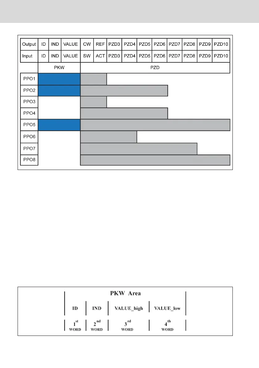
Output Master output
Input Master input
ID Parameter identifier
IND Parameter index mark
VALUE Parameter value
CW Control word
SW Status word
REF Reference / Setting frequency
ACT Actual output frequency
Fig. 14-2: PPO telegram type
PKW parameter area
PKW parameter area description
This data area is composed of ID, IND, VALUE_high and VALUE_low, as shown in
figure below. They are used to read or modify the parameter of a parameter of a
frequency converter, but only one parameter can be read or modified each time.
When master sends request and slave responds, bit definition for each specific
word in PKW area is shown in the tables below. If a frequency converter fails to
execute PKW area request command, an error code will be returned to the mas-
ter in VALUE_low. Refer to tab. 14-33 "PKW area error codes" on page 280 for
details.
Fig. 14-3: PKW area data format
Bosch Rexroth AG
Communication
EFC x610 Series
278/389
DOK-RCON03-EFC-X610***-IT05-EN-P
 Loading...


