Phase loss protection
Error code 'IPH.L' is displayed on the operating panel in case of input phase loss
error occurs; error code 'OPH.L' is displayed on the operating panel in case of
output phase loss error occurs.
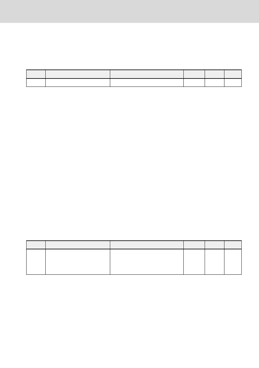
Code Name Setting range Default Min. Attri.
C0.28 Phase loss protection mode 0...3 3 – Run
● 0: Both input and output phase loss protection active
● 1: Only input phase loss protection active
● 2: Only output phase loss protection active
● 3: Both input and output phase loss protection inactive
An input phase loss can also be triggered by line voltage imbalance or deteriora-
tion of DC-bus capacitors. The input phase loss cannot be detected in the fol-
lowing conditions:
● No run command
● The output current is lower than 30 % of converter rated current
● During motor deceleration
The output phase loss has a dead zone in the following cases:
● The output frequency is lower than 1.00 Hz
● During DC-braking
● During restarting with speed capture
● During motor parameters auto-tuning
● Wrong settings of parameter C1.07 'Motor rated current'
Analog Input Broken Wire Detection
Code
Name Setting range Default Min. Attri.
E1.61 Broken wire protection
0: Inactive
1: Warning
2: Error
0 – Stop
If '4…20 mA' or '2…10 V' is selected for all analog inputs (AI1, AI2 and EAI on I/O
card), then this function can detect the input missing possibly due to the cable
disconnection. Once the broken wire is detected, the frequency converter can
either continue running with warning (Warning code: Aib-) or stop with error in-
dication (Error code: AibE), which can be configured by parameter E1.61.
For 4…20 mA analog input, the detection level is 10 % of 4 mA.
For 2…10 V analog input, the detection level is 7.5 % of 2 V.
EFC x610 Series
Bosch Rexroth AG
Functions and Parameters
DOK-RCON03-EFC-X610***-IT05-EN-P
203/389

 Loading...


