This mode refers to voltage / frequency control with curve defined according
to actual application, which is used for special loads of dewatering machines,
centrifuges, etc.
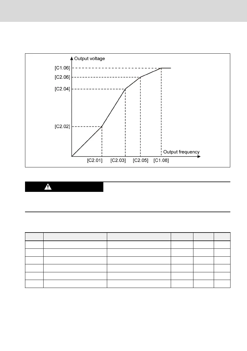
Fig. 12-61: User-defined V/f curve
Excessively high voltage at low-frequency may cause the motor overheat or dam-
age, and the frequency converter stall overcurrent or overcurrent protection.
User-defined V/f curve configuration
Code
Name Setting range Default Min. Attri.
C2.01 V/f frequency 1 0.00...[C2.03] Hz 0.00 0.01 Stop
C2.02 V/f voltage 1 0.0...120.0 % 0.0 0.1 Stop
C2.03 V/f frequency 2 [C2.01]...[C2.05] Hz 0.00 0.01 Stop
C2.04 V/f voltage 2 0.0...120.0 % 0.0 0.1 Stop
C2.05 V/f frequency 3 [C2.03]...[E0.08] Hz 50.00 0.01 Stop
C2.06 V/f voltage 3 0.0...120.0 % 100.0 0.1 Stop
Each of the three V/f frequency points is limited by the neighboring V/f frequen-
cy points. In general, each V/f frequency point shall be set according to follow-
ing sequence: 0 ≤ [C2.01] ≤ [C2.03] ≤ [C2.05] ≤ [C1.08]
There are two modes of user-defined V/f curve:
● User-defined V/f curve when [C2.05] ≤ [C1.08]
EFC x610 Series
Bosch Rexroth AG
Functions and Parameters
DOK-RCON03-EFC-X610***-IT05-EN-P
217/389
 Loading...


