12.7 Special Functions
12.7.1 Counter Function
The internal counter counts the input pulses received from 'digital input' and
compares it with the setting value of 'Counter middle value' or 'Counter target
value'.
The 'Counter middle value arrival' or 'Counter target value arrival' output signal
will be indicated via DO1 or Relay 1 output when the counter value equals to
that of setting value.
The counter is cleared and the DO1 or Relay 1 output signal is reset by a valid
edge signal of another digital input defined as 'Counter reset'.
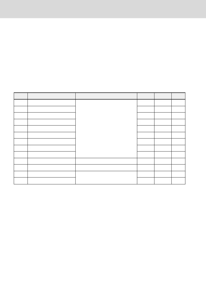
Code Name Setting range Default Min. Attri.
E1.00 X1 input
39: Counter input
40: Counter reset
35 – Stop
E1.01 X2 input 36 – Stop
E1.02 X3 input 0 – Stop
E1.03 X4 input 0 – Stop
E1.04 X5 input 0 – Stop
H8.00 EX1 input 0 – Stop
H8.01 EX2 input 0 – Stop
H8.02 EX3 input 0 – Stop
H8.03 EX4 input 0 – Stop
E2.80 Counter middle value 0...[E2.81] 0 1 Run
E2.81 Counter target value [E2.80]...9,999 0 1 Run
E2.01 DO1 output setting 16: Counter target value arrival
17: Counter middle value arrival
1 – Stop
E2.15 Relay 1 output selection 1 – Stop
Example:
X1 input is defined as '39: Counter input'.
X2 input is defined as '40: Counter reset'.
The wiring is shown as the figure below:
Bosch Rexroth AG
Functions and Parameters
EFC x610 Series
172/389
DOK-RCON03-EFC-X610***-IT05-EN-P
 Loading...


