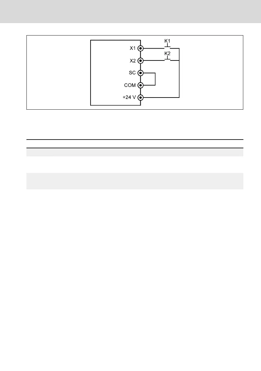
Fig. 12-38: Digital input configuration
Connected K1 to X1, and set [E1.00] = '39: Counter input'.
Connected K2 to X2, and set [E1.01] = '40: Counter reset'.
K1 K2 Running status Status
Inactive Inactive – –
Edge Inactive
Counter value
= [E2.80] / [E2.81]
Internal counter value stays at [E2.80] / [E2.81]
Digital output is active
Edge Edge Counter is reset
Internal counter value is reset to ‘0’
Digital output is inactive
Tab. 12-15: Counter function
'DO1 output' or 'Relay 1 output' signal and status are as below:
● [E2.01] / [E2.15] = '16: Counter target value arrival'
When the internal counter receives from 'X1 input' the number of input pulse,
which equals to [E2.81] 'Counter target value'.
● [E2.01] / [E2.15] = '17: Counter middle value arrival'
When the internal counter receives from 'X1 input' the number of input pulse,
which equals to [E2.80] 'Counter middle value'.
The signal is reset by the next valid edge signal of 'X2 input' which is defined as
'40: Counter reset'.
Example:
[E2.80] = 5, [E2.81] = 8
The output behavior is described as below:
EFC x610 Series
Bosch Rexroth AG
Functions and Parameters
DOK-RCON03-EFC-X610***-IT05-EN-P
173/389

 Loading...


