14.3.4 Communication Mapping Register Address Distribution
Frequency converter parameter address
Frequency converter parameter registers correspond to the function codes one-
to-one. Reading and writing of related function codes can be achieved through
reading and writing of the contents in frequency converter parameter registers
via Modbus communication. The characteristics and scope of reading and writ-
ing function codes are in compliance with the frequency converter function code
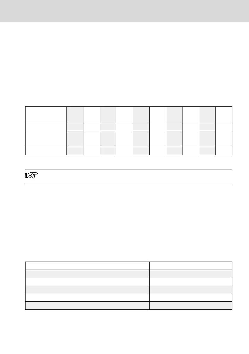
description. The address of a frequency converter parameter register is com-
posed of a higher byte representing the function code group and a lower byte
representing the index in the group. The groups are mapped as follows:
Address
high byte
0x00 0x20 0x21 0x22 0x23 0x30 0x31 0x32 0x33 0x34
Group b0 C0 C1 C2 C3 E0 E1 E2 E3 E4
Address
high byte
0x35 0x38 0x39 0x60 0x61 0x68 0x69 0x40 0x41 0x10
Group E5 E8 E9 H0 H1 H8 H9 U0 U1 d0
Tab. 14-22: Frequency converter parameter registers
Parameters of the monitoring group (Group d0) are always write-pro-
tected.
Examples:
To read out the module temperature (d0.20) of EFC x610 frequency converter,
use register address 0x1014 (0x10 = Group d0, index 0x14 = 20).
To set V/f curve mode (C2.00) of EFC x610 frequency converter, use register ad-
dress 0x2200 (0x22 = Group C2, index 0).
Access to a non-existing function code will be acknowledged with exception
code 3 (see chapter 14.3.3 "Modbus Function and Message Format" on page
259).
Frequency converter register address
Register
Address
Communication control register 0x7F00
Communication state register 0x7FA0
Additional status register 0x7FA1
Fault status register 0x7FB0
Communication frequency setting register 0x7F01
Tab. 14-23: Frequency converter register address
EFC x610 Series Bosch Rexroth AG
Communication
DOK-RCON03-EFC-X610***-IT05-EN-P
267/389

 Loading...


