Input Channel Parameter
Input signal Unit Min Typ. Max
Allowed input voltage V -3 - 30
Logical 0 (Low) V - - 5
Logical 1 (High) V 15 - -
Input current mA 2 - 15
Impedance kΩ - 3.8 -
Filtering time
①
ms - > 3 -
Response time
②
ms - < 20 -
Tab. 19-6: Input channel parameter
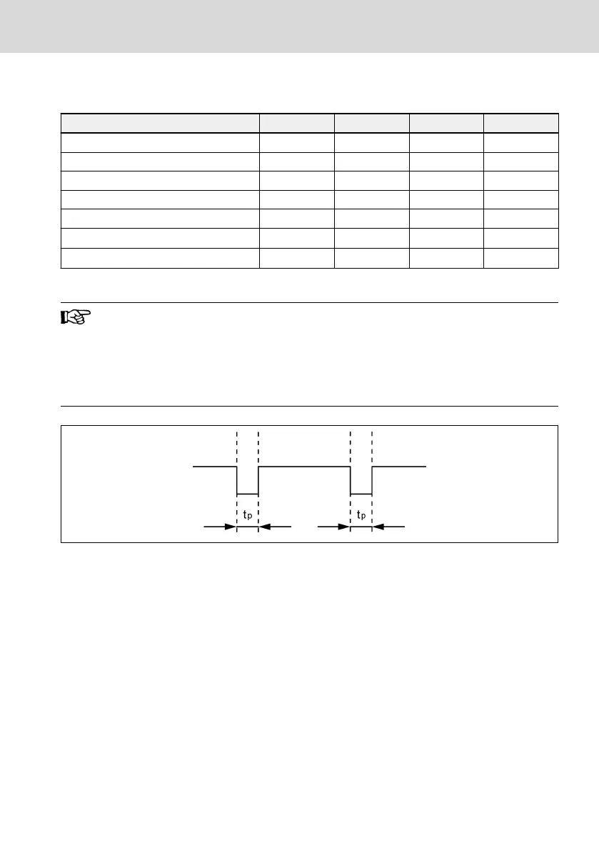
①
: Filtering time means when a low time test pulse (as shown in fig-
ure below, "t
p
" is the filtering time) input to the channel, there is no
influence to the operation and indication of the device.
②
: Response time means time from the de-energization of each STO
input channel to the power semiconductor stage shut off the out-
puts of the device.
Fig. 19-22: Filtering time
EFC x610 Series Bosch Rexroth AG
Appendix
DOK-RCON03-EFC-X610***-IT05-EN-P
383/389

 Loading...


