Removal and replacement of ADU modules
8-16 Chapter 8: Service & maintenance 98-137654-A
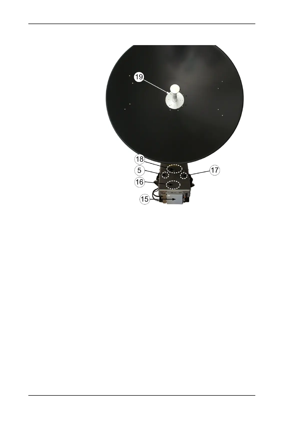
15. DC-Motor Driver Module for Azimuth (DDM).
16. Azimuth motor (not visible on photo).
17. Azimuth encoder (not visible on photo).
18. Rotary joint (not visible on photo).
The cable signals for the ADU (DC power, internal modem
communication, RX) to and from the ACU have to be ported from
the stationary platform to the azimuth rotating part of the ADU.
This is done via the rotary joint.
19. Feed horn.
The feeder horn carries the mirror centred of the dish and in the
correct distance. Thereby the signal from the satellite is reflected
by the dish and picked up by the mirror.
Before contacting your service partner check the LEDs on all
modules. See LEDs of the ADU modules on page 8-9 and LEDs in the
ACU on page 8-9.
Figure 8-8: Above Deck Unit modules (continued)
SAILOR100TM.book Page 16 Tuesday, January 29, 2013 2:44 PM