Removal and replacement of ADU modules
98-137654-A Chapter 8: Service & maintenance 8-61
8888
Service & maintenance
8.5.8 Replacing the Zero Reference Module (ZRM)
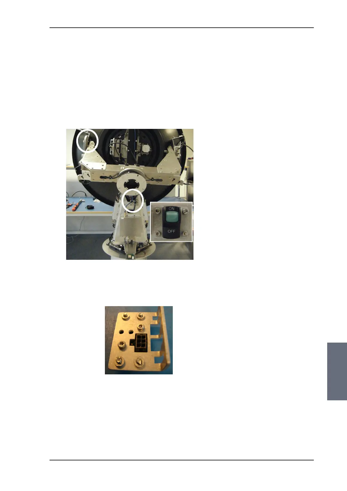
The ADU has the following identical ZRMs, one for each drive wheel
(each axes):
• X Elevation ZRM
• Elevation ZRM
• Azimuth ZRM
The ZRM has a Hall sensor detecting a zero point (small magnet
mounted on the drive wheel). The zero point signal of the ZRM is
sent to the PCM to be used in the orientation of the ADU.
For step-by-step instructions see:
Removing the X Elevation ZRM on page 8-62
Inserting a new X Elevation ZRM on page 8-64
Removing the Elevation ZRM on page 8-64
Figure 8-74: Location of the Zero Reference Modules (ZRM)
Figure 8-75: Zero Reference Module (ZRM)
3 ZRM, 2 as
shown, 1 on the
front, bottom.
SAILOR100TM.book Page 61 Tuesday, January 29, 2013 2:44 PM



 To Next Page