Removal and replacement of ADU modules
98-137654-A Chapter 8: Service & maintenance 8-17
8888
Service & maintenance
8.5.0.1 Tools needed
Have the following tools ready at hand when starting to replace
modules:
• 4x150 mm Allen key (located inside the service door of the ADU)
• Torx 20 screw driver
• Flat head screw driver
• 8 mm open-end spanner
• 11 mm open-end spanner
• 18 mm open-end spanner
• Acoustic frequency meter
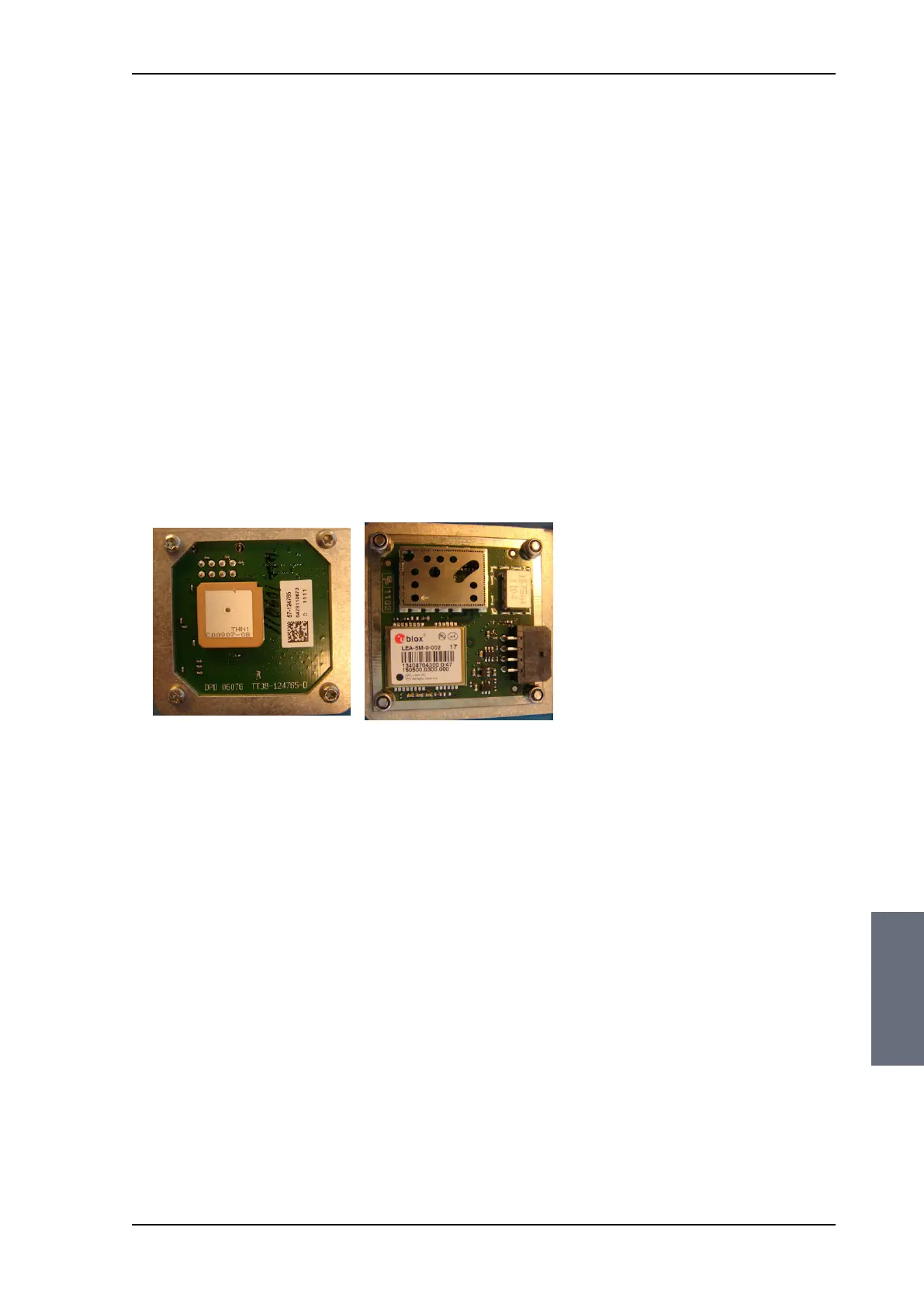
8.5.1 Replacing the GPS module
The GPS Module is equipped with a receiver antenna (on top side)
receiving the signals transmitted from the GPS satellites (low orbit),
typical 10-12 are visible above the horizon. On the opposite side
(bottom side) of the GPS Module the engine is located. It converts
the GPS satellite signals into current position data (latitude,
longitude and level). A minimum of 4 GPS satellites should be seen
by the GPS Module to produce a valid position.
The GPS module is identical to the ones used in Thrane & Thrane
SAILOR FleetBroadband products.
Figure 8-9: GPS module
Top view
Bottom view
SAILOR100TM.book Page 17 Tuesday, January 29, 2013 2:44 PM