Removal and replacement of ADU modules
98-137654-A Chapter 8: Service & maintenance 8-31
8888
Service & maintenance
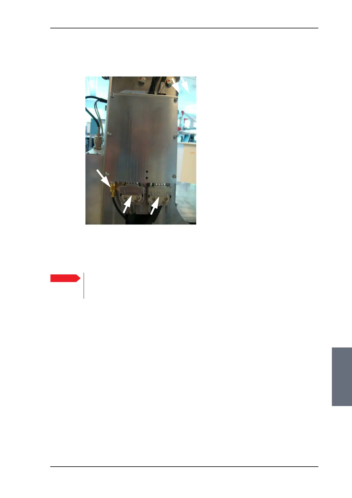
4. Disconnect the 2 connectors at the top, then the 2 SUB-D
connectors at the bottom, then the SMA connector at the bottom
(left) of the PCM.
5. Remove the 4x4 mm Allen screws (thread size M5) (all become
visible when the connectors are removed) and remove the PCM.
To insert a new PCM follow the instructions above in reverse order.
Figure 8-30: Removing the PCM — connectors
Important
After installing a new PCM you must update the
calibration data. For instructions see Updating
TIM/PCM calibration data on page 8-78.
SMA
SAILOR100TM.book Page 31 Tuesday, January 29, 2013 2:44 PM