Removal and replacement of ADU modules
8-66 Chapter 8: Service & maintenance 98-137654-A
5. Press in and turn the elevation locking pin (available in some
antennas) to locked position.
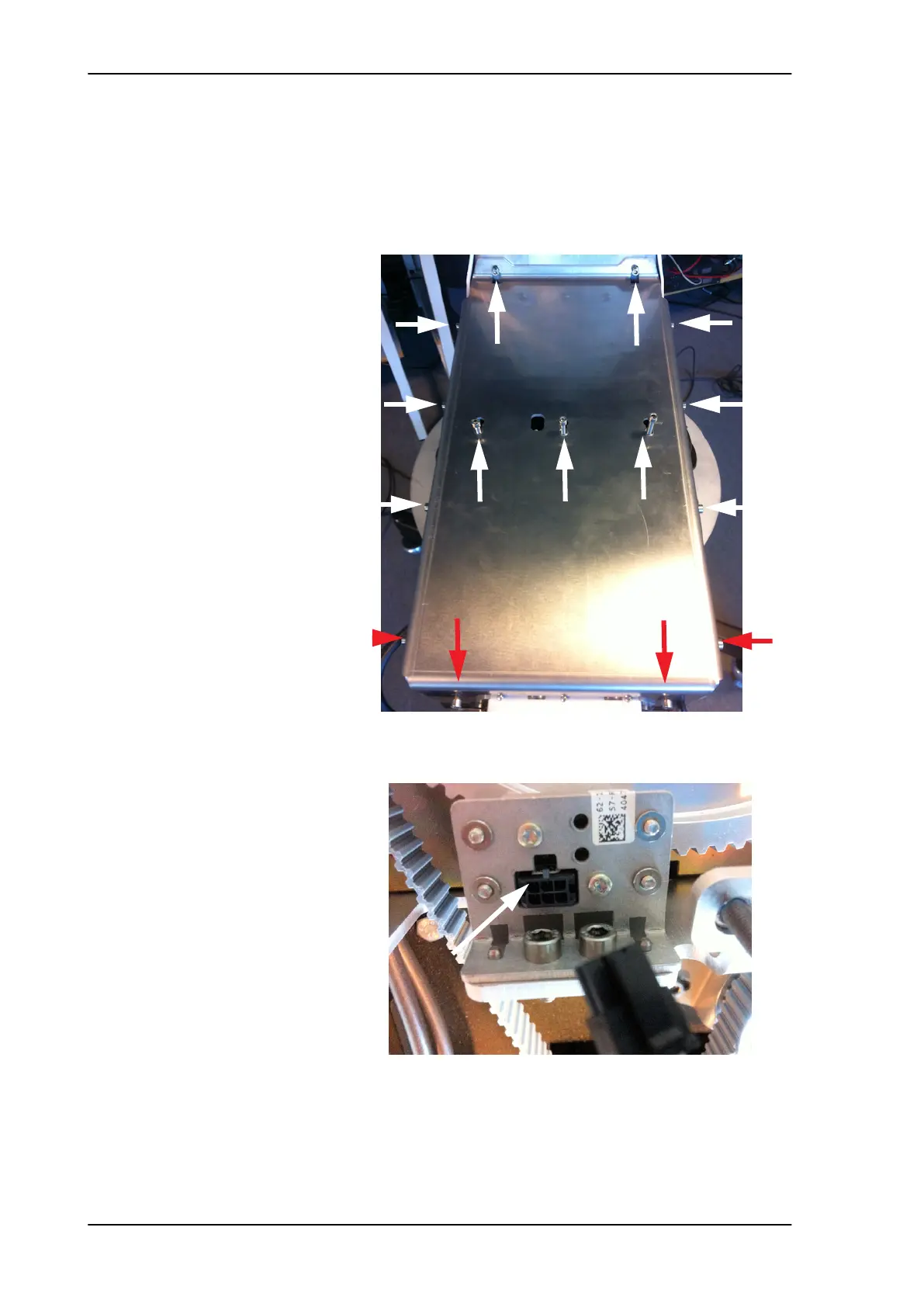
6. Loosen the 15x4 mm Allen screws (the 3 Allen screws on top are
longer than the rest) on the cover over the azimuth drive
modules, and remove the cover (lift and slide).
7. Disconnect the connector from the Azimuth ZRM.
Figure 8-80: Azimuth ZRM, remove cover
Figure 8-81: Azimuth ZRM, disconnect connector
L=35 mm L=35 mm L=35 mm
SAILOR100TM.book Page 66 Tuesday, January 29, 2013 2:44 PM