Interfaces of the SAILOR 100 Satellite TV ACU
98-137654-A Chapter 4: Interfaces 4-3
4444
Interfaces
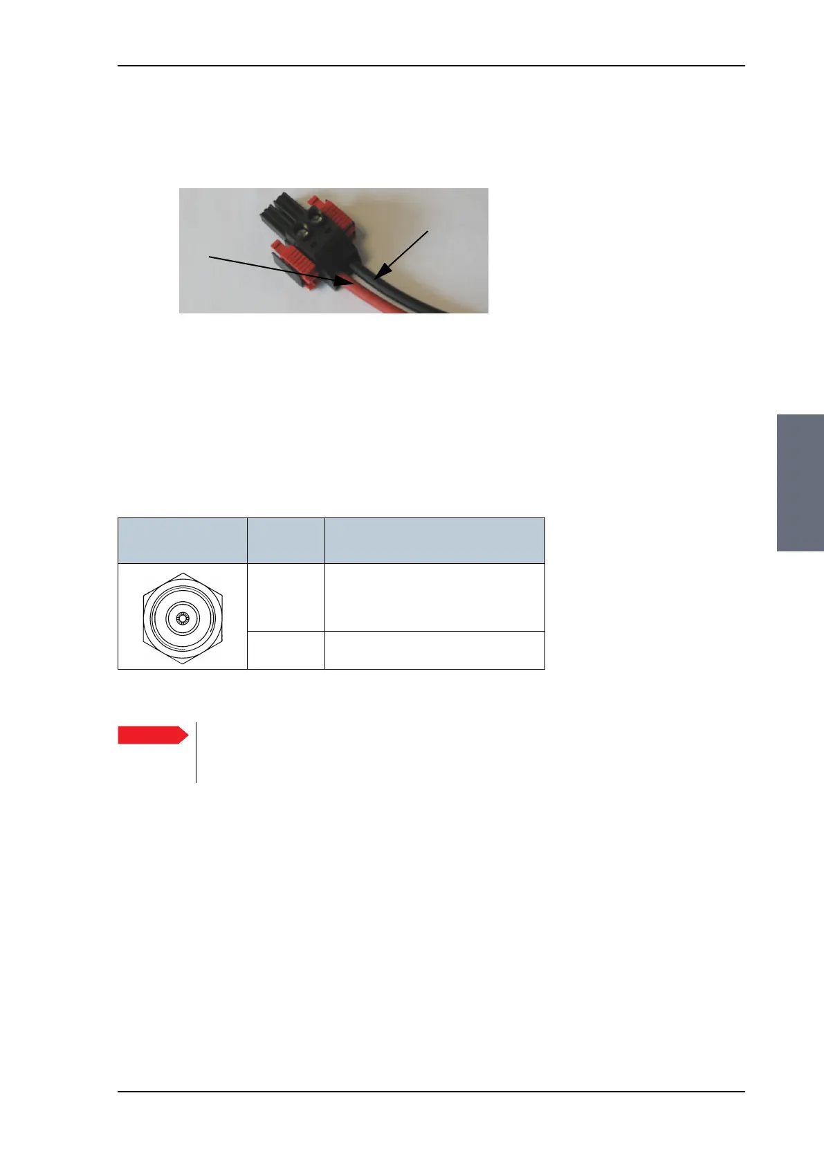
The connector for DC input is included in the delivery. Insert the
power cable as shown below, and plug in the connector. Use the
two red clamps to fasten the connector.
For more information about power supply and power requirements
see Connecting power on page 5-1.
4.1.4 ADU connector
There is just one cable from the ACU to the ADU. This is used to
power the ADU, handle all communication between ACU and ADU,
and deliver the Rx signal.
4.1.5 Rx connector
Connector for internal use (cable already connected).
Figure 4-3: DC Input connector with power cable
Black
Red
(right)
(left)
Outline
(on the ACU)
Conductor Pin function
Inner DC to ADU
ACU to ADU internal communication
Rx (950 — 5450 MHz)
Outer GND (Shield)
Table 4-2: N connector, outline and pin assignment
Important
Do not use TNC connectors on the ADU antenna cable
or on pigtails. TNC connectors cannot carry the DC
current for operating the ADU.
SAILOR100TM.book Page 3 Tuesday, January 29, 2013 2:44 PM