Installation of the Control Panel
98-137654-A Chapter 3: Installation 3-25
3333
Installation
point, making sure the shield of the connector is properly connected
to the rack.
3.4.2.2 Ground stud at the ACU
To ensure that the ACU is grounded – also if the ADU cable is
disconnected from the ACU, connect an extra ground wire from the
rack to the ground stud on the ACU. This ground wire must be a
heavy wire or braid cable with a larger diameter than the coax
cable.
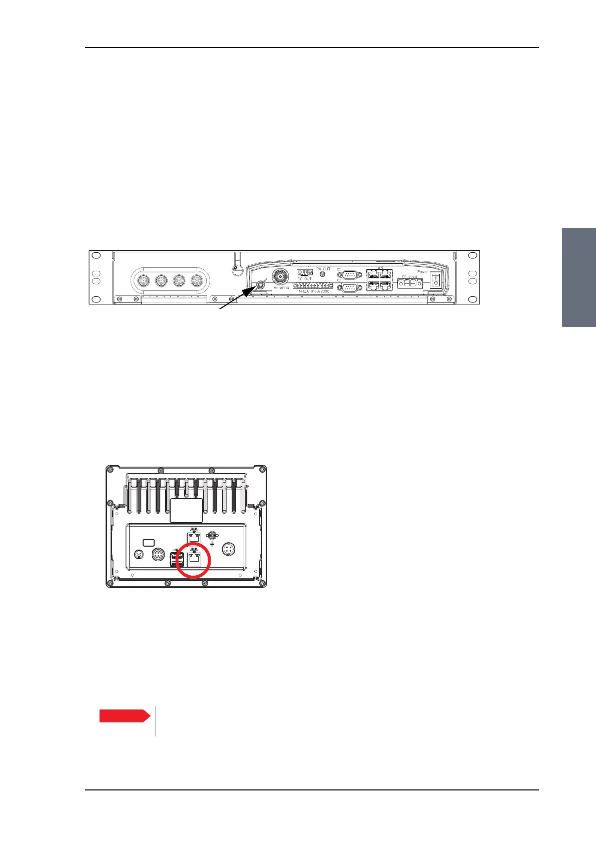
3.5 Installation of the Control Panel
For instructions how to install the Control Panel see the installation
manual for the Control Panel, see the table List of Related
Documents on page 1-2 .
To connect the Control Panel to the ACU do as shown below:
1. Connect an Ethernet cable to the Ethernet connector at the back
of the Control Panel.
2. Connect the other end of the Ethernet to LAN 4 of the ACU (rear
connector panel), possibly through a switched network.
Figure 3-23: ACU, ground stud
Figure 3-24: Connecting the Control Panel to the ACU, LAN4
on ACU
Connect to
Ethernet on
LAN 4 on ACU.
Important
If the Control Panel is connected directly to the ACU, you must enable
DHCP Server on LAN 4, see Configuring the LAN network on page 6-25.
SAILOR100TM.book Page 25 Tuesday, January 29, 2013 2:44 PM