Removal and replacement of ADU modules
8-30 Chapter 8: Service & maintenance 98-137654-A
8.5.5 Replacing the Pedestal Control Module
(PCM)
The PCM controls the antenna dish and the Polarization Mechanism
Assembly with the three DC motors and a step motor.
Communication between the PCM and ACU is done via the TIM. The
TIM is also controlled by the PCM via a parallel interface cable.
The PCM is the communication master of the ADU serial-bus
connecting the DDM, PMM and ISM. Communication to the GPS
Module and power to all modules is via S-bus.
The PCM has two LEDs for status and troubleshooting:
• Power LED: green or Off
• Service LED: green or red
To replace the PCM, do as follows:
1. Open the service hatch by releasing the two latches with Torx
screws.
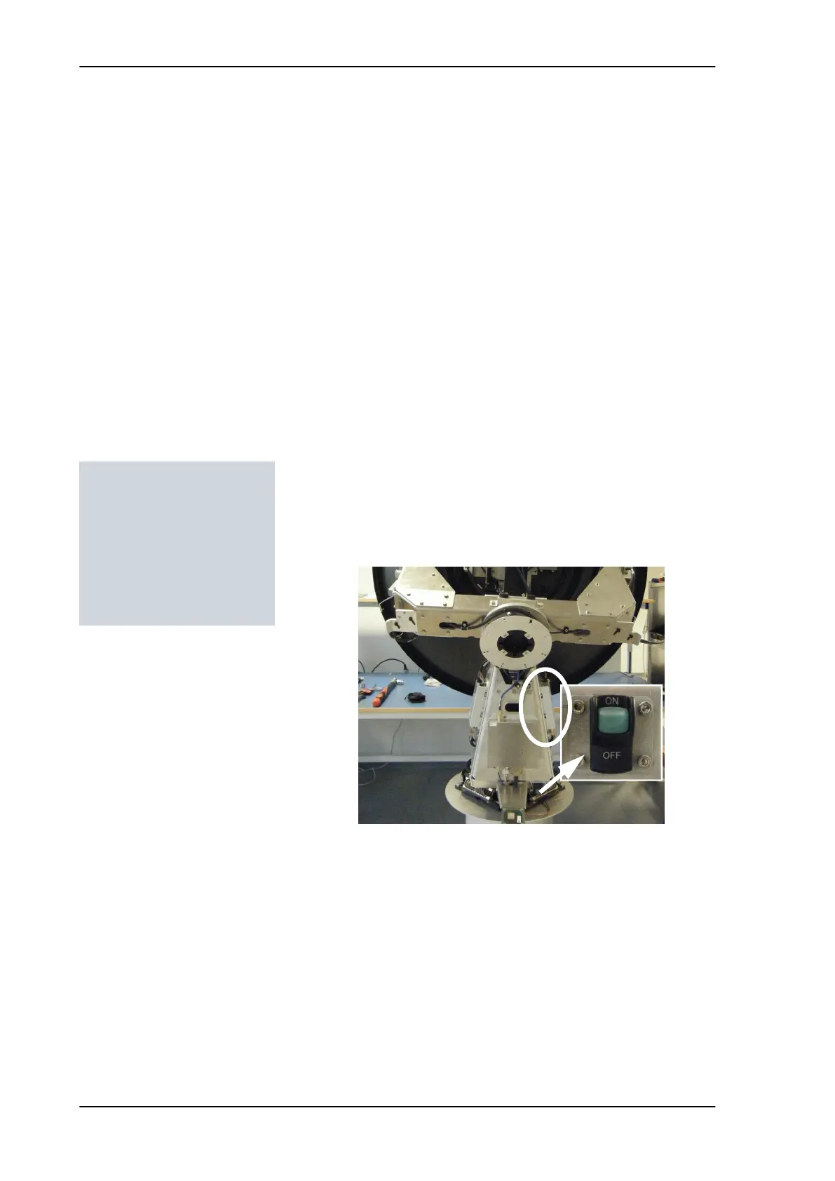
2. Switch off the power to the antenna on the service switch.
3. Rotate the antenna pedestal so that the Pedestal Control Module
(PCM) faces the service hatch.
Tools needed:
• 4 x 150 mm Allen key
(located inside the
service door of the ADU)
• Flat head screw driver
• 8 mm open-end spanner
Figure 8-29: Location of the PCM
SAILOR100TM.book Page 30 Tuesday, January 29, 2013 2:44 PM