Installation of the ADU
98-137654-A Chapter 3: Installation 3-21
3333
Installation
Otherwise, follow standard procedures for cabling in ship
installations.
3.3.1.1 Maximum allowed RF loss in the ADU cable
Maximum allowed cable loss 25 dB at 5450 MHz. This is to ensure
optimum performance of the system.
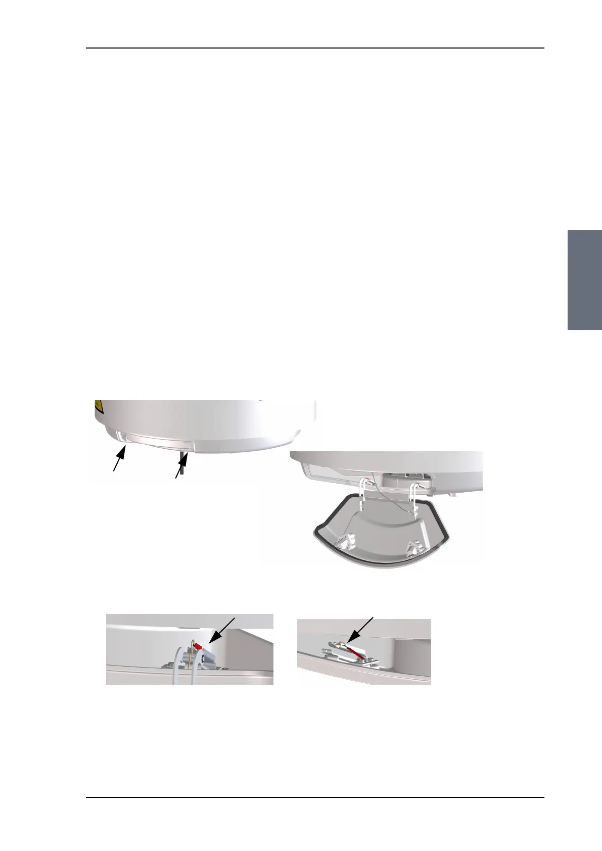
3.3.2 Opening and removing the service hatch
Open the hatch to access the antenna modules. The two latches of
the service hatch must be locked by fastening the two screws in the
latches with a Torx TX20 screw driver to protect the ADU modules
against unauthorised access.
You can remove the hatch for better mobility when servicing the
antenna. Do as follows to open and remove the service hatch:
1. With a Torx TX20 screw driver, remove the two screws locking the
latches.
2. Pull open the two latches and let the lid fall open.
3. Remove the 2 split pins and park them.
4. Pull the service hatch free.
Figure 3-18: Opening the service hatch
Open with Torx TX20
Figure 3-19: Removing the 2 split pins
SAILOR100TM.book Page 21 Tuesday, January 29, 2013 2:44 PM