SAILOR 100 Satellite TV system
2-8 Chapter 2: Introduction 98-137654-A
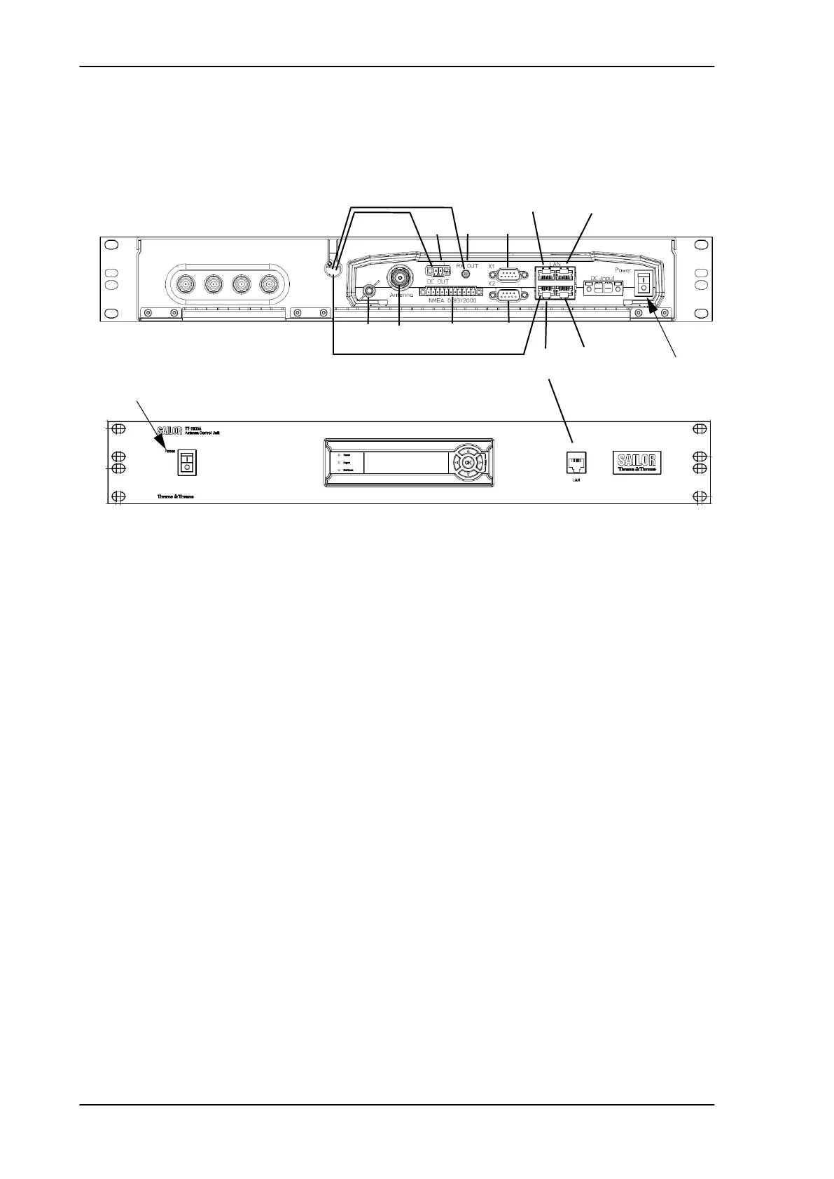
2.1.2.1 ACU interfaces
The ACU has the following interfaces and switch:
• 4 x F-connector for TV outputs (75 Ohm).
• Ground stud
• N-connector for ADU cable (50 Ohm).
• Connector for DC out (for internal use).
• SMA connector for RF RX output (50 Ohm) (for internal use).
• Multi connector for NMEA interfaces (for input from GPS compass
or Gyro compass).
• X1 connector (reserved for future use).
• X2 connector (reserved for future use).
• 4 x LAN ports for system operation and maintenance and control
interface to Control Panel and SAILOR Transmodulator, plus 1 x
LAN port at the front.
• Power connector.
• On/Off power switch
2.1.2.2 Service friendly
You can do remote diagnostics and service with the ACU. Its built-in
test equipment checks constantly the ACU’s modules for proper
functioning, it monitors and logs for all modules. It performs POST
Figure 2-6: SAILOR 100 Satellite TV ACU, connector overview
NMEA
(reserved)
(reserved)
LAN 1
Power
On/Off
LAN 2
LAN 3
LAN 4
.
Service port
TV output
Set to On
ADU
V
Cable to front LAN connector
Low
H
Low
V
High
H
High
RX
DC out
Cables to internal connector
Ground
Set to On
SAILOR100TM.book Page 8 Tuesday, January 29, 2013 2:44 PM