Power cable selection
98-137654-A Chapter 5: Connecting power 5-3
5555
Connecting power
5.2.3 Power cable recommendations
5.2.3.1 Overview
The ACU is delivered with a power connector (PCB plug-in
connector, female plug, Weidmuller, Part number 1930050000),
which accepts wires up to AWG10/6 mm
2
.
• When installing the power cable, install positive and negative
supply wires closely together side by side to keep cable
inductance low.
• Ensure that cable inductance for the selected cable at the desired
length is less than 50 uH. Approximately 50 m maximum length.
5.2.3.2 Calculating the maximum power cable length
For 24 VDC operation, the total impedance must be max. 60 mOhm
(R
max
for SAILOR 100 Satellite TV with SAILOR Transmodulator and
max. 90 mOhm (R
max
) for SAILOR 100 Satellite TV without SAILOR
Transmodulator), including the source impedance in the ship
installation (R
source
).
The total impedance is made up of the following:
• Source impedance in the ship installation
• Impedance of the selected power cable
To calculate the maximum cable extension, do as follows:
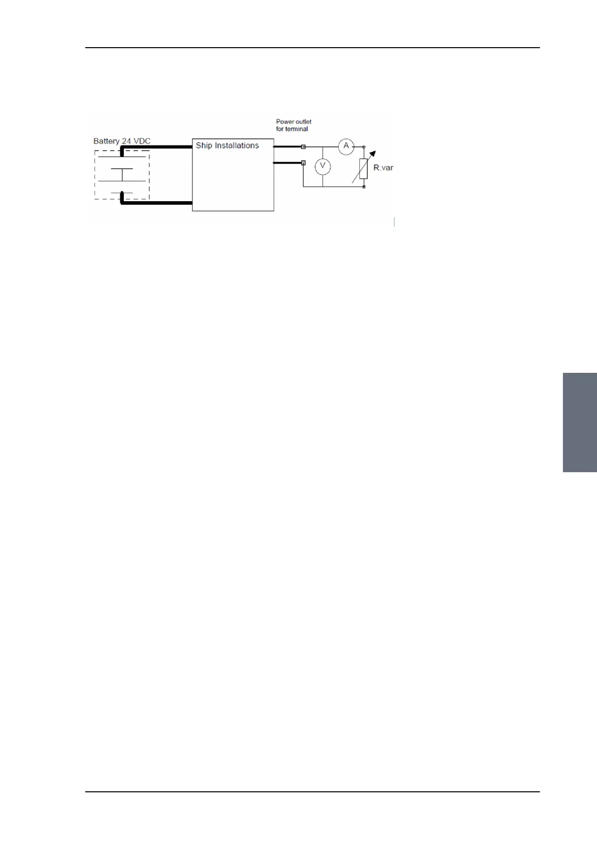
1. First measure the source impedance in the ship installation as
shown in Measuring the ship source impedance on page 5-2.
2. Find the resistance per meter (Rwire) for the cable type you are
going to use.
Figure 5-1: Measuring the ship source impedance
SAILOR100TM.book Page 3 Tuesday, January 29, 2013 2:44 PM