Removal and replacement of ADU modules
8-68 Chapter 8: Service & maintenance 98-137654-A
When the antenna dish is moved by the motors and ships motions,
in all its plans the ISM provides the information regarding these
movements.
This information is based on rate gyro and accelerometers mounted
in the ISM.
The information is passed on to the PCM.
The ISM has two LEDs for status and troubleshooting:
• Power LED: green or Off
• Service LED: green or red
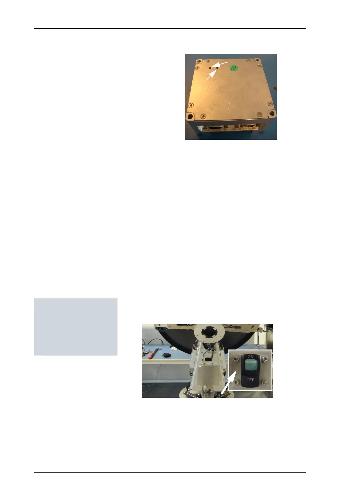
8.5.9.1 Removing the ISM
1. Open the service hatch by releasing the two latches with Torx
screws.
2. Switch off the power to the antenna on the service switch.
3. Press in and turn the elevation locking pin (only available from
S/N TBD) to locked position.
4. Rotate the antenna so that you can reach the ISM.
5. Loosen the 4x4 mm Allen screws (thread size M5).
Figure 8-84: Inertial Sensor Module (ISM)
Power LED
(green or red)
(green)
Tools needed:
• 4 x 150 mm Allen key
(located inside the
service door of the ADU)
• Flat head screw driver
SAILOR100TM.book Page 68 Tuesday, January 29, 2013 2:44 PM