Removal and replacement of ADU modules
98-137654-A Chapter 8: Service & maintenance 8-27
8888
Service & maintenance
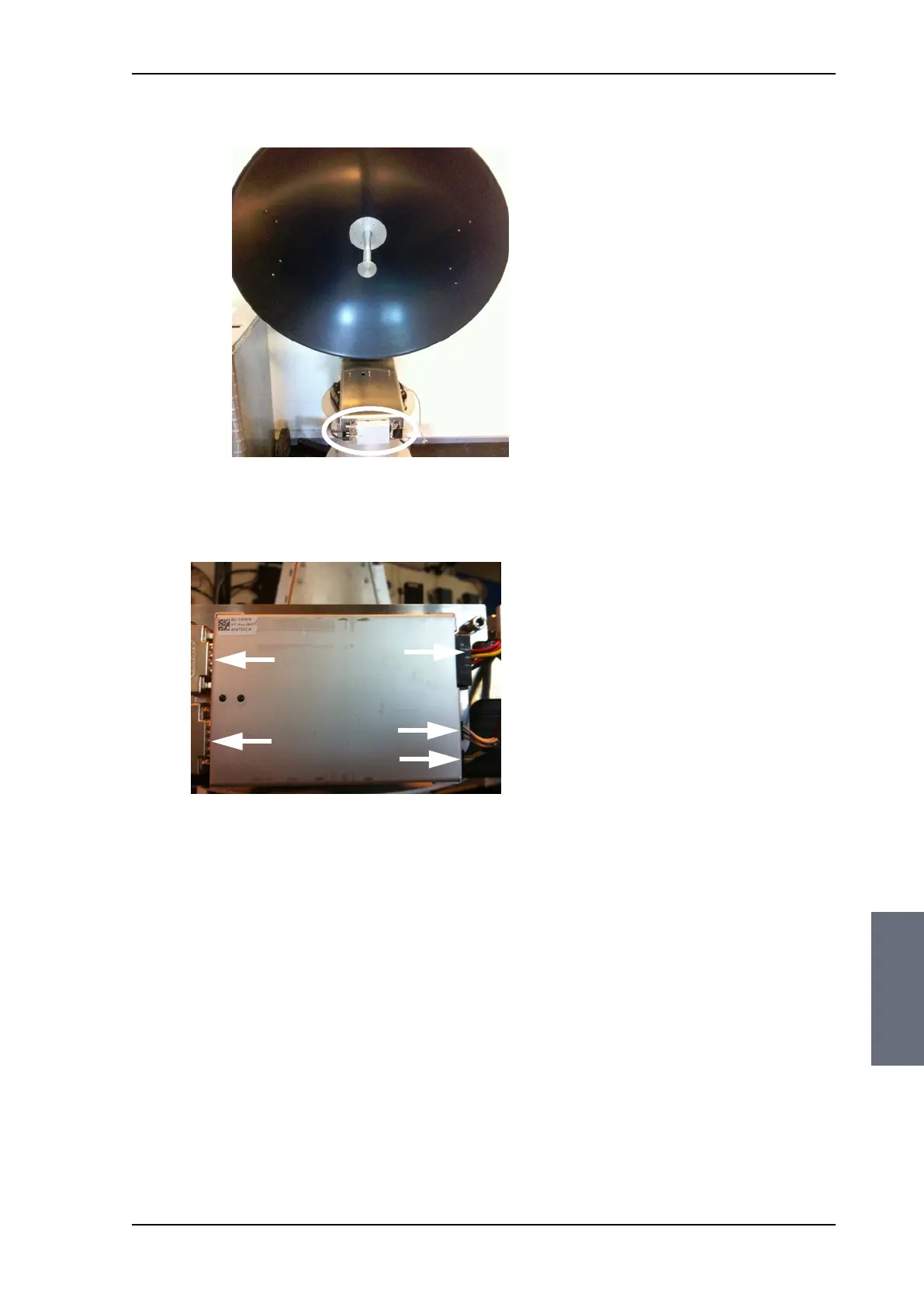
5. Disconnect the 3 connectors at the right of the Azimuth DDM,
then the 2 SUB-D connectors at the left of the Azimuth DDM.
6. Remove the 4x4 mm Allen screws (thread size M5) (visible when
the connectors are removed) and remove the Azimuth DDM.
8.5.3.6 Inserting a new Azimuth DDM
To insert a new Azimuth DDM follow the instructions above in
reverse order.
Figure 8-24: location of the Azimuth DDM
Figure 8-25: Azimuth DDM, connectors
SAILOR100TM.book Page 27 Tuesday, January 29, 2013 2:44 PM