Removal and replacement of ADU modules
98-137654-A Chapter 8: Service & maintenance 8-67
8888
Service & maintenance
8. Loosen the 2x4 mm Allen screws.
9. Slide out the Azimuth ZRM.
8.5.8.6 Inserting a new Azimuth ZRM
To insert a new Cross Elevation ZRM follow the instructions above in
reverse order.
8.5.9 Replacing the Inertial Sensor Module (ISM)
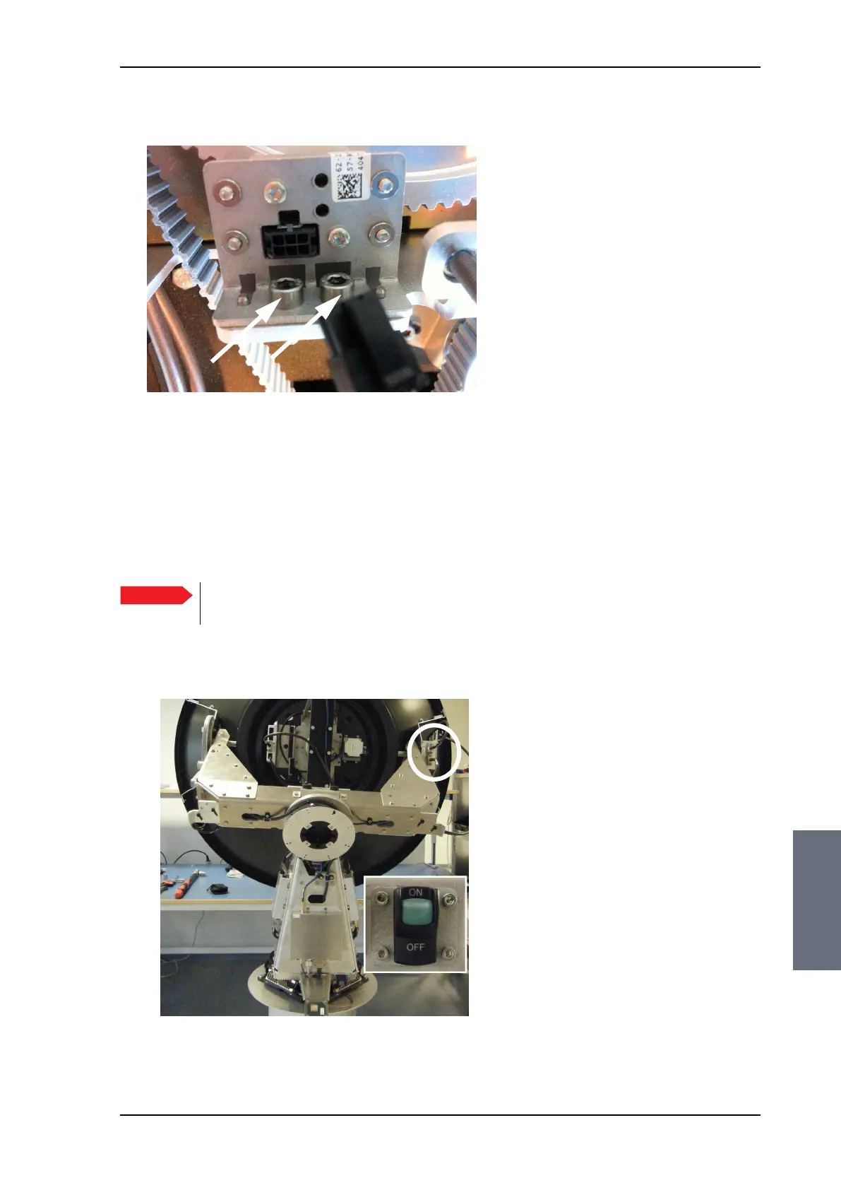
Figure 8-82: Azimuth ZRM, disconnect connector
Important
It is very important that you slide the ZRM all the way
into the guide pins.
Figure 8-83: Location of the Inertial Sensor Module (ISM)
SAILOR100TM.book Page 67 Tuesday, January 29, 2013 2:44 PM