Installation check list: ACU, connectors and wiring
98-137654-A Chapter 7: Installation check 7-3
7777
Installation check
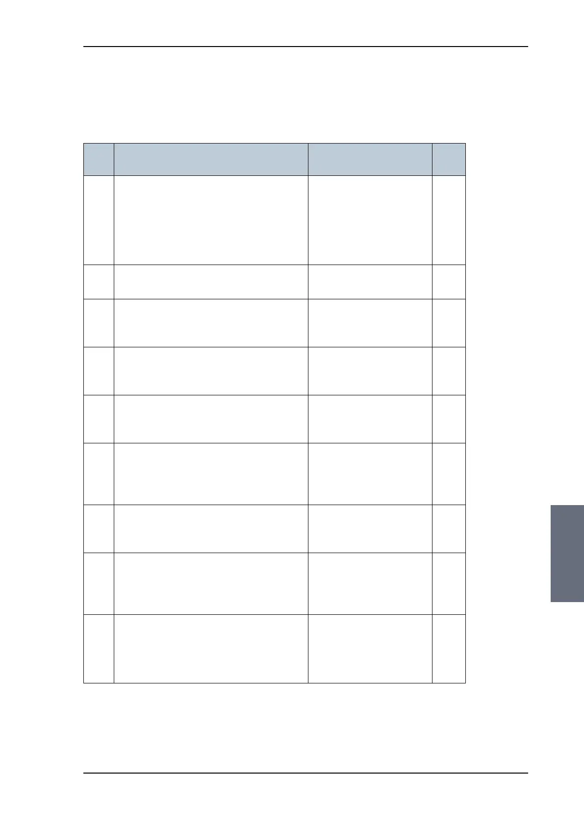
7.2 Installation check list: ACU,
connectors and wiring
Step Task
Verification and further
information
Done
1.
Check that the ACU is grounded correctly. See Grounding the ACU
on page 3-24
and
Grounding and RF
protection on page B-1.
2.
Make sure you strain relieved the cables. See Installing the ACU on
page 3-23.
3.
Check that the ADU antenna N-connector
is properly connected with the 50 Ohm RF
cable.
Visual inspection of the
cover plate at the bottom
of the ADU.
4.
Check that the ACU antenna N-connector
is properly connected with the 50 ohm RF
cable.
Visual inspection of the
connector panel of the
ACU.
5.
Check that the ACU's cable at RX OUT is
looped back into the ACU to feed the
destacker.
Visual inspection of the
connector panel of the
ACU.
6.
Check that the ACU's V Low, H Low, V
High and H High are connected correctly
to external TV equipment, e.g.
Multiswitch or SAILOR Transmodulator.
Visual inspection of the
connector panel of the
ACU and connected TV
equipment.
7.
Check that the ACU's cable at DC OUT is
looped back into the ACU to feed the
destacker.
Visual inspection of the
connector panel of the
ACU.
8.
Check that the Control Panel is connected
to the ACU using LAN 4, possibly through
a switched network.
Visual inspection of the
Ethernet connection
between the Control
Panel and the ACU.
9.
Check that the ADU's NMEA 0183
connector is connected to the NMEA 0183
bus of the vessel using the included
multi-connector
Visual inspection of the
connector panel of the
ACU connector.
Table 7-2: Installation check list: ACU, connectors and wiring
SAILOR100TM.book Page 3 Tuesday, January 29, 2013 2:44 PM