Removal and replacement of ADU modules
98-137654-A Chapter 8: Service & maintenance 8-41
8888
Service & maintenance
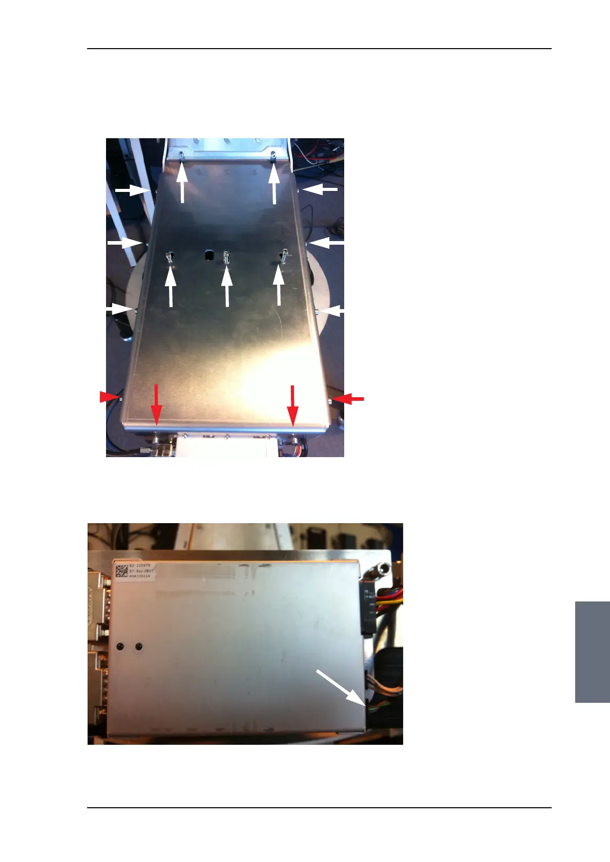
6. Loosen the 15x4 mm Allen screws (the 3 Allen screws on top are
longer than the rest) on the cover over the azimuth drive
modules, and remove the cover (lift and slide).
7. Disconnect the 6-pin connector (colored wires) from the Azimuth
DDM.
Figure 8-44: Azimuth encoder, remove cover
Figure 8-45: Azimuth DDM, disconnect connector
L=35 mm L=35 mm L=35 mm
SAILOR100TM.book Page 41 Tuesday, January 29, 2013 2:44 PM