Installation of the ACU
3-24 Chapter 3: Installation 98-137654-A
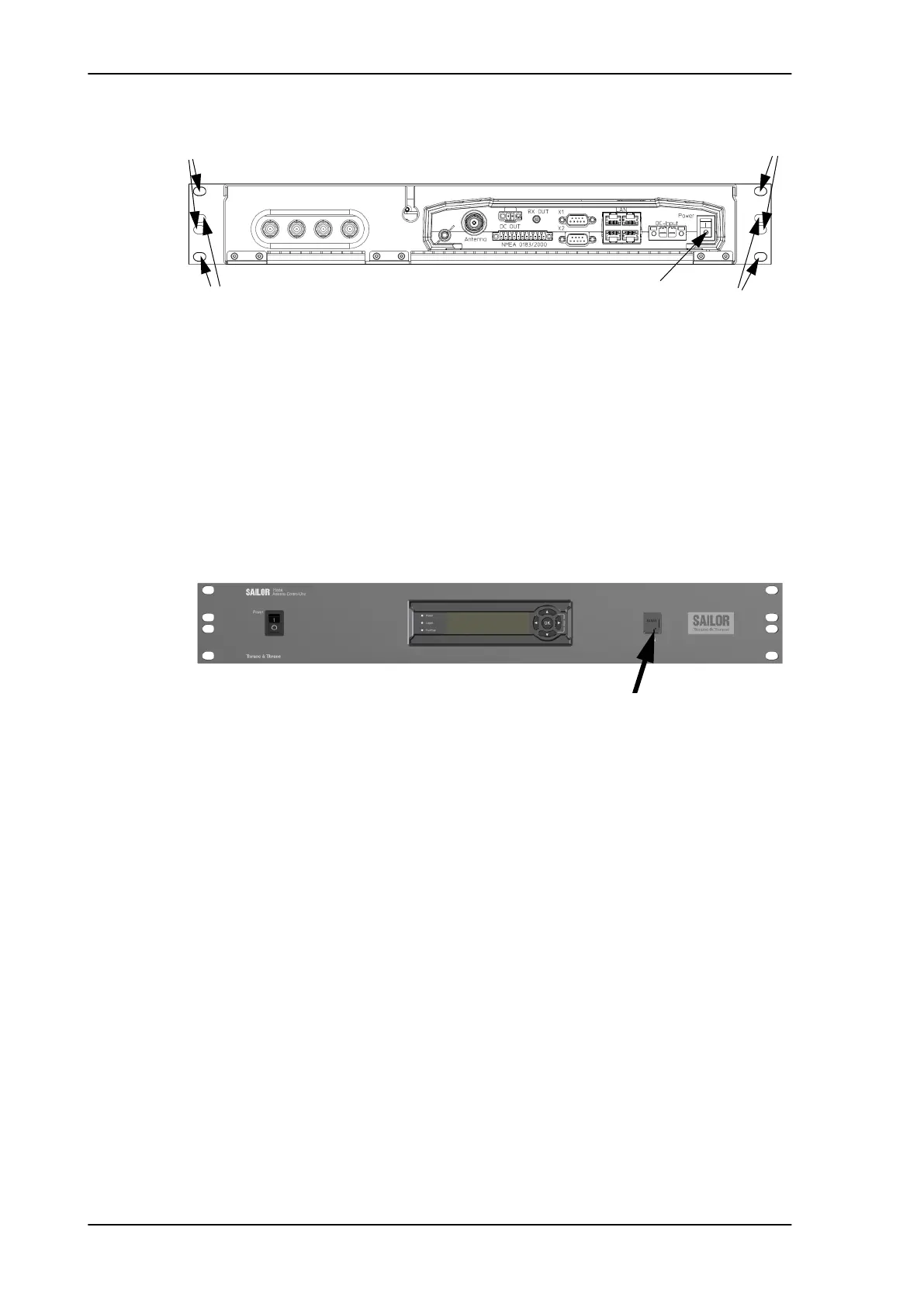
4. Set the On/Off switch at the back of the ACU to On. Then you can
use the On/Off switch at the front panel.
3.4.1.1 Connectors of the ACU
For a description of the connectors see Connector panel — overview
on page 4-2. The ACU has additionally a LAN connector at the front
for accessing the service port from the ACU front panel.
For information on wiring 24 VDC power see DC Input connector on
page 4-2. For more information about power supply and power
requirements see Connecting power on page 5-1.
3.4.2 Grounding the ACU
Make sure that the grounding requirements are met. See the
appendix Grounding and RF protection on page B-1 for details about
grounding.
3.4.2.1 ADU cable
The ADU is connected to the ACU with the ADU cable (coax cable)
with an N connector at both ends. For information on ADU
grounding, see Grounding the ADU on page 3-22.
At the ACU end, it is strongly recommended to ground the ADU
cable. Use a short cable from the ACU to a grounding point in the
rack and connect the short cable to the ADU cable at this grounding
Figure 3-21: ACU, On/off switch at the back
Power
.
TV output
Set to On
ADU
A
A
B
B
Figure 3-22: ACU, LAN connector at the front: Service port
Service port connected to front
SAILOR100TM.book Page 24 Tuesday, January 29, 2013 2:44 PM