Removal and replacement of ADU modules
98-137654-A Chapter 8: Service & maintenance 8-19
8888
Service & maintenance
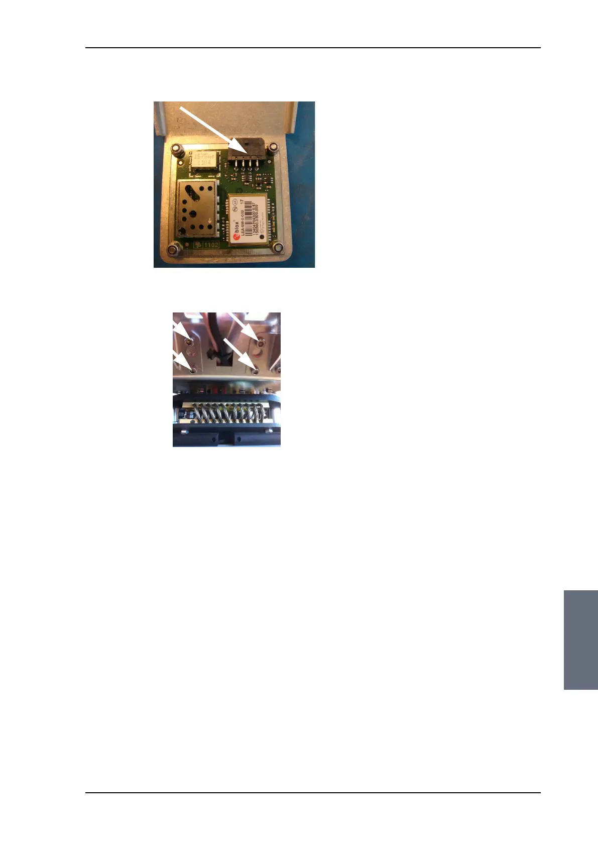
4. Disconnect the GPS module from the TIM.
5. Loosen the 4x4 mm Allen screws (thread size M5).
6. Lift the complete GPS module including the mounting arm from
the pedestal.
To insert a new GPS module follow the instructions above in reverse
order.
Figure 8-12: Connector for GPS PCB
Figure 8-13: Screws on GPS module
SAILOR100TM.book Page 19 Tuesday, January 29, 2013 2:44 PM