Vista Digital Mixing System
2-4 Desk Operation SW V3.3 Date printed: 05.08.03
[2]
[1]
[3a]
[4]
[5a]
[6]
[5b]
[3b]
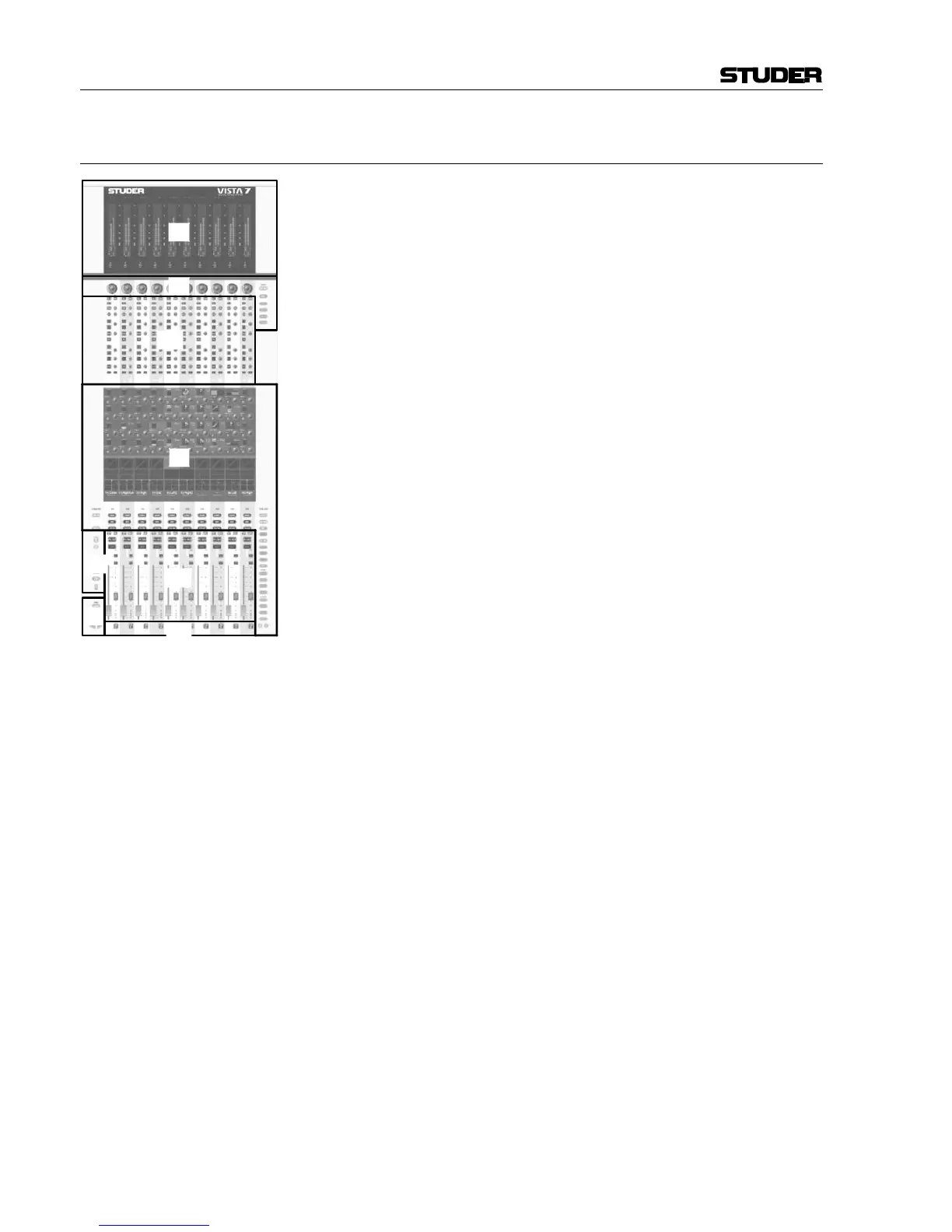
2.1 Fader Bay Overview
A fader bay can be subdivided into six areas:
• Area [1] contains meters dedicated to each channel strip.
• Area [2] contains rotary controls dedicated to each channel strip. This
rotary control can have one out of six functions, assigned by the at-
tached viewing keys. Unless the bay is currently locked, changing the
assigned function affects the whole console, not only that specific bay.
• Areas [3a] and [3b] contain various controls, dedicated to each channel
strip: Audio functions on/off, Copy/Paste, Selectors, and other standard
elements, such as Fader, Mute, PFL etc.
• Area [4] hosts the Vistonics™ element with 10 × 4 on-screen rotary
controls and a touch screen area. Some rounded keys are located next to
the screen in order to change parameter views on the Vistonics™
screen. The Vistonics™ module can act as a channel-strip-specific con-
trol, dedicating four rotary controls as well as their associated bitmaps
and graphical displays of the most important settings to each channel
strip. It can also act in a sort of “central assign section”-way, occupying
any number of Vistonics™ controls, in order to access multiple pa-
rameters of one specific channel strip. In that case the control elements
of adjacent channels are used as well.
• Areas [5a] and [5b]: These keys are generically used either to select
channels or influence any operation on them.
• Area [6] contains controls that are determining which DSP channels are
currently visible on that bay. It is possible to either change the whole
console to display a different section, or just let that specific bay change
to show some different DSP channels.