Vista Digital Mixing System
2-14 Desk Operation SW V3.3 Date printed: 05.08.03
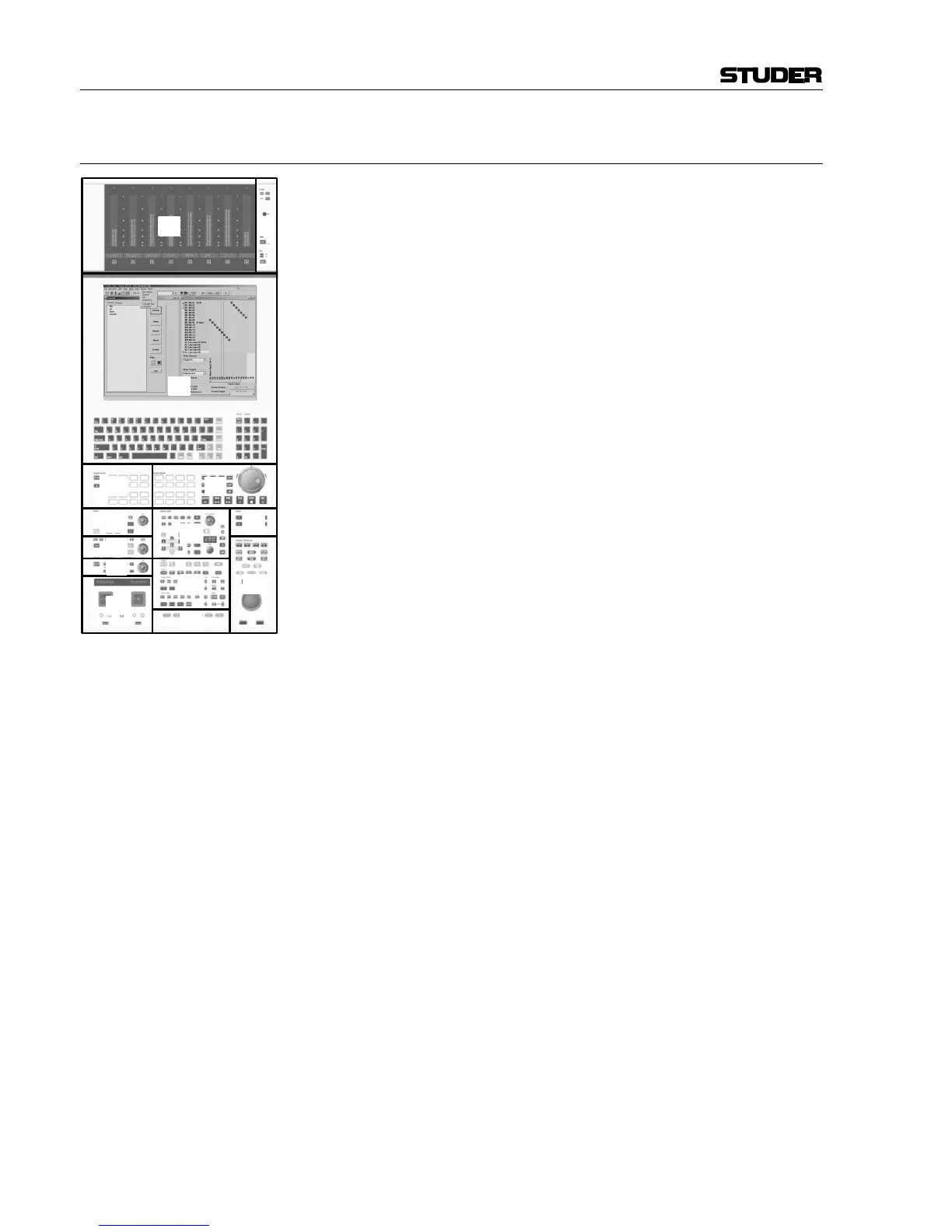
2.3 Control Bay Overview
The control bay is divided into 14 different areas:
Area [1] is used for system power up/down, meter settings, and talkback
microphone.
Area [2] contains the monitor metering with VFD bargraph meters. Please
note that Vista 6 is equipped with a gain reduction display or a custom
meter bridge.
Area [3] is the TFT display with the Graphic Controller (GC) application
and a keyboard with numerical keypad.
Area [4] contains the 9-pin machine control (Vista 7 only).
Area [5] is a monitoring source selector (applicable to all controllable
rooms).
Area [6] is the studio monitoring control unit (Level, Solo, Dim, Mute...).
Area [7] is the control room (CR) monitoring control unit (Level, Solo,
Dim, Mute...).
Area [8] contains spare keys (F1...F3, F4...F7) for future functions and/or
options, the clipboard library key (F4), and the external VGA switch (F8).
Area [9] is the talkback section.
Area [10] is used for:
• Control group setup,
• Headphones control, and
• it contains desk-related global switches (In1/In2 switches dedicated to
input, group, monitor channels). Please note that these switches may be
de-activated in the GC’s Vista Settings window.
Area [11] is the global automation control for AutoTouch+ automation
(Vista 7 only).
Area [12] holds:
• A trackball for Graphic Controller operation
• Hardware keys for selecting major pages in the Graphic Controller
• Dedicated keys for snapshot operation.
In area [13] the motorized joysticks for panning are located (optional),
and area [14] is the section navigator with keys for navigation (section
jumps/scrolling) through the console.