Vista Digital Mixing System
Date printed: 05.08.03 SW V3.3 Desk Operation 2-9
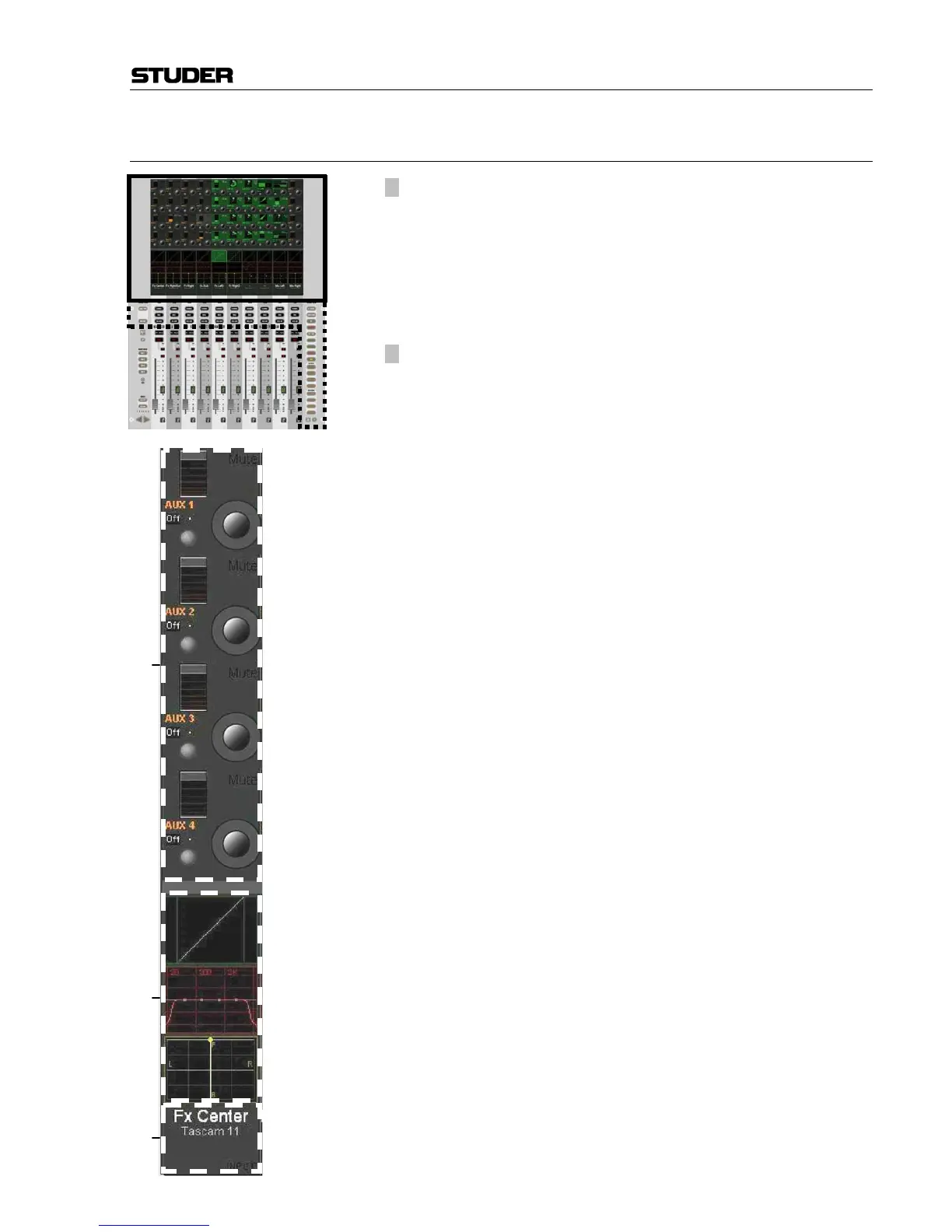
2.2.5 Area 4 – Vistonics™
[30] Vistonics™ Rotary Control Area
Each rotary control is grouped with a key to form a control element. These
control elements are sometimes used in a channel-related manner, dedicat-
ing four control elements to each channel strip; sometimes, neighboring
channels are used in order to show a complete parameter set of one single
channel. This is the case when touching any graphical display of EQ, dy-
namics, or pan, but also when activating VIEW: MISC [33] or
VIEW: CHANNEL [34].
[31] Vistonics™ Touch Screen Area
Graphical indication of dynamics, equalizer and pan. Touching the graph-
ics will open up all corresponding parameters on the rotary control area.
This section is also able to display bus assignment. Two modes are avail-
able: Bus assignment as a “bubble view” to give an overview over the
whole console, or bus assignment of a specific channel (one per bay).
The graphical pan display may vary depending on the configured panning
function or format. (2-CH Stereo Pan, Multi-format Pan, VSP).
[32] Generic Display Area
This area is used to display all sorts of information. The following is con-
tinuously displayed:
• Inherited label (top line). This corresponds to the USER label of the
connected source (can be edited in the GC’s Global Patch window).
• Switchable label (second line). Normally this is set to USER labels, but
might be changed by pressing GLOBAL VIEW: LABEL TYPE [36]. If set
to USER label, the device label of the connected source is being dis-
played (e.g. “Mic1, StA”).
• Indication of channel type by color coding of the lower half as well as
writing the type in the bottom right corner.
The following information pops up when appropriate:
• Fader value in dB, when touched (or “held” in dynamic automation
mode)
• Graphical representation of fader values in automation mode (replay
value of last mix pass and currently set value at the same time)
• Graphical representation of current setting and previewed snapshot at
the same time.
• Automation mode of the fader.
• Indication if the fader was dynamically automated while pressing
AUTOMATION VIEW [184].
• Numerical indication of the current peak meter value if metering is in
PEAK: HOLD CONT mode, or of the overload value if OVERLOAD: HOLD
is active.
• Vista 6: N–1 indication and bus number.
Touching the upper half (for input channels, multi-track input channels,
multi-track monitor channels): Opens the GC’s General Patch window,
showing the channel input position of the selected channel..
Touching the lower half (for all channels): Opens the GC’s General Patch
window, showing the direct output position of the selected channel.
[32]
[31]
[30]