Vista Digital Mixing System
Date printed: 05.08.03 SW V3.3 Desk Operation 2-5
2.2 Fader Bay Details
¹ Each key marked with this symbol can be activated either momentarily or
latching. Pressing this key for a short time will make it latching. Holding it
down for a longer period of time will reverse its function automatically
upon key release.
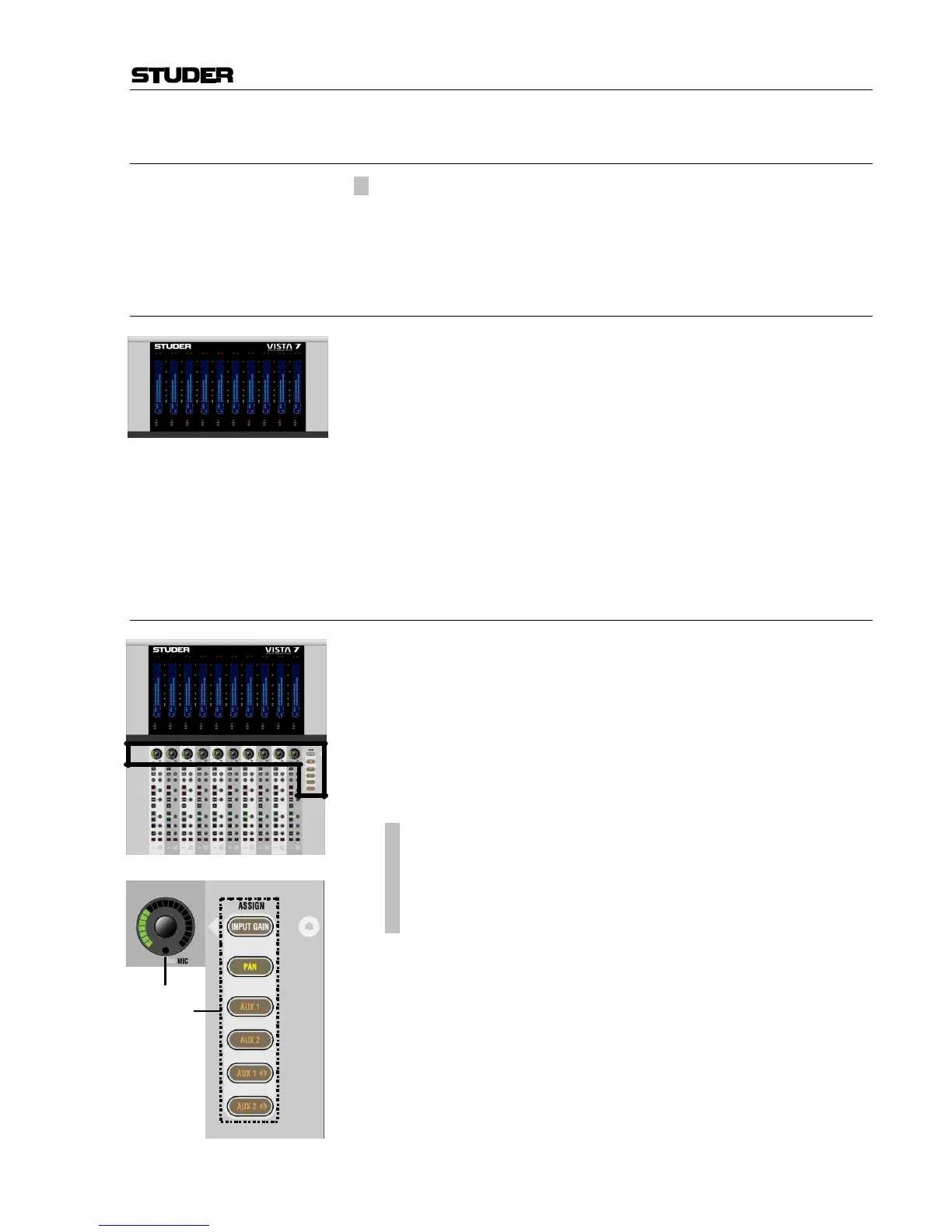
2.2.1 Area 1 – Channel Metering
Level Meters
Show digital peak values with indication of headroom (one blank bar),
clipping (red LED), peak hold (temporary or continuous), gain reduction
(expander/gate: bottom left, compressor/limiter: bottom right), meter tap
point (the indicated meter value is either the input, post fader, or direct
output level). The bargraph meters may be split to display the left and right
signals of a stereo channel.
Note: It is possible to use the red LED above the meters to indicate headroom
rather than clipping. This is set in the GC’s “Meter/Generator ” window.
Vista 6: If the channel is an N–1 owner, the right-hand bargraph shows
the output signal level. If stereo signals are present, the meter indicates the
larger level of the two channels.
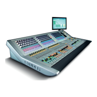
2.2.2 Area 2 – Channel Control
[1] “Dedicated” Rotary Controls
The user may put one out of six available functions onto this rotary con-
trol. This function is selected by pressing one of the six ASSIGN keys [2].
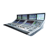
When ASSIGN: INPUT GAIN is selected and a Studer microphone preampli-
fier is connected, the analog gain will be controlled before the ana-
log/digital converters. Otherwise the rotary control will adjust digital input
gain. In any case, further control is available on the Vistonics™ module.
The control of a Studer microphone preamplifier is indicated by a small
red MIC LED at the bottom of the rotary control.
[2]
¹ ASSIGN: INPUT GAIN
¹ ASSIGN: PAN
¹ ASSIGN: AUX1
¹ ASSIGN: AUX2
¹ ASSIGN: AUX1 S
¹ ASSIGN: AUX2 S
Function selection for the “dedicated” rotary control:
• Input Gain (standard digital gain, or analog gain if a Studer microphone
preamplifier is connected)
• Left/Right Pan
• AUX mono 1 and 2 level
• AUX stereo 1 and 2 level
Normally, the function changes throughout the whole console. If the bay is
locked, only the assignment in the corresponding bay changes.