TLS-450 Setup and Operation Screens Manual
7
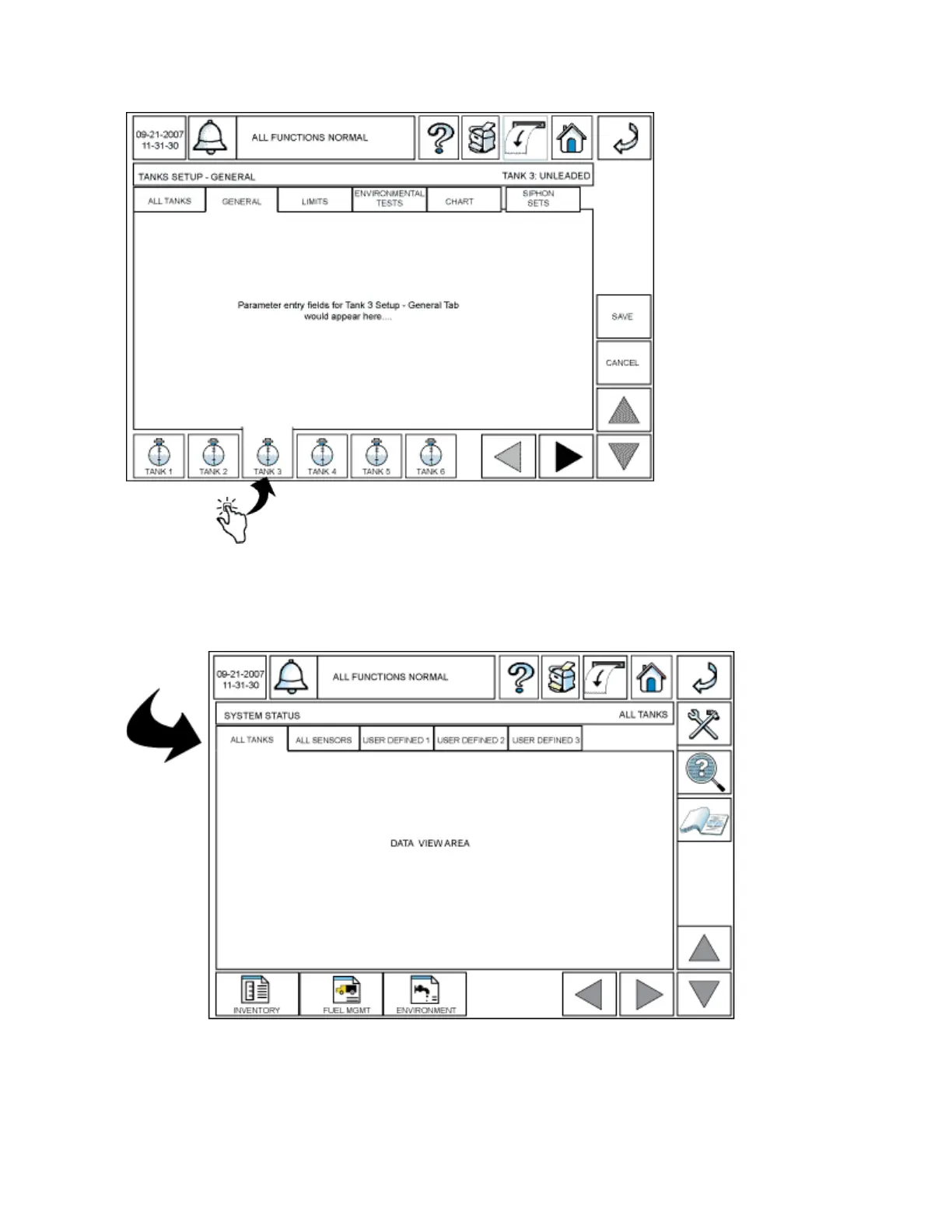
The data area displays the information associated with any selected setup, report or diagnostic screen.
Tabs at the top of the data area (All Tanks, All Sensors, User Defined 1, etc. in the diagram below), if
present, provide access to related data screens when touched.
 Loading...


