TRANSMISSION
M6040, M7040, WSM
3-S26
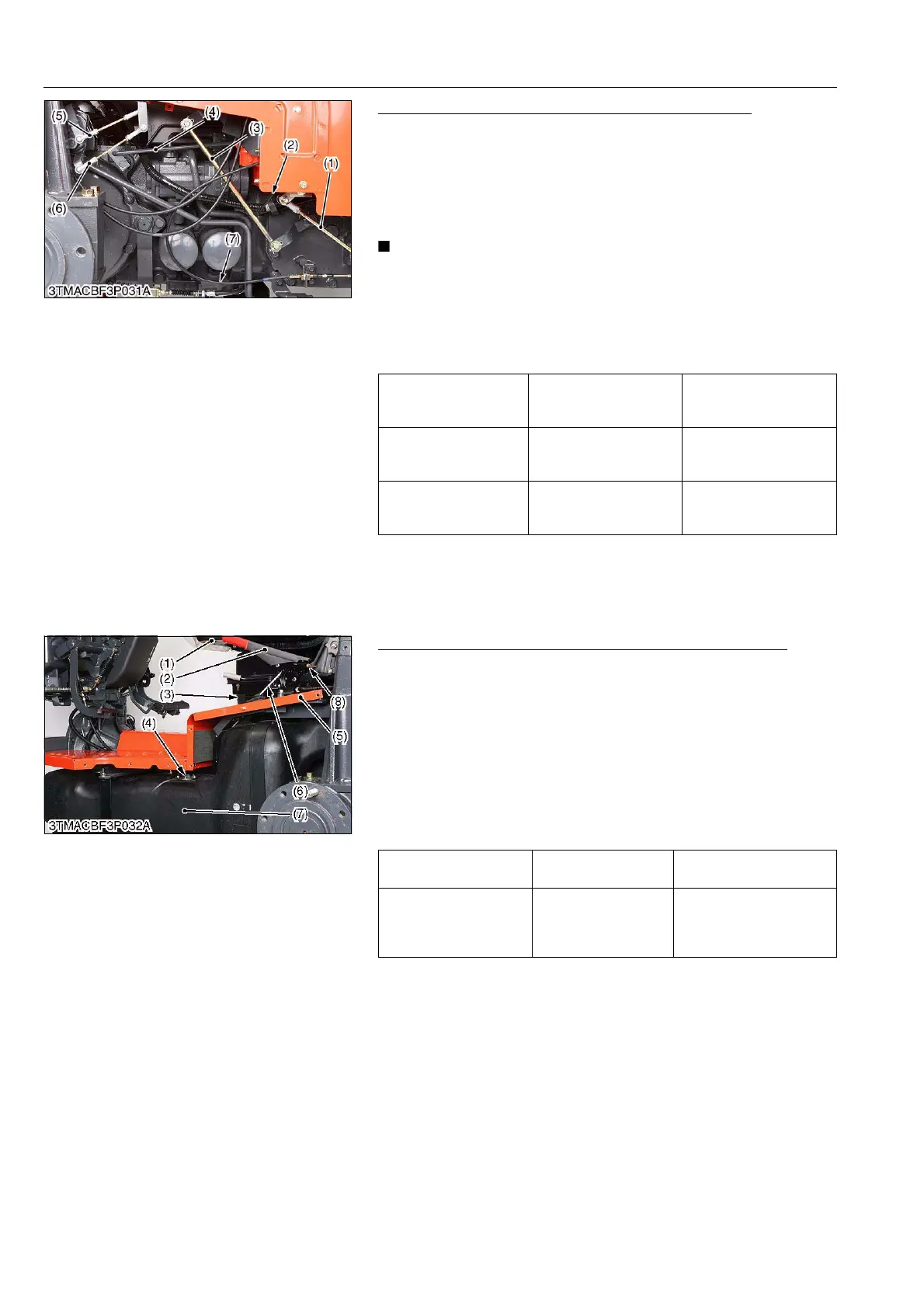
Hydraulic Control Rod, Shift Change Rod and Wire
1. Disconnect the position control rod (6) and draft control rod (5).
2. Remove the differential lock rod (4).
3. Disconnect the main shift change rod (1) and H-L change shift
rod (3).
4. Disconnect the select wire (7).
5. Disconnect the accelerator wire (2).
• After assembling check the speed change lever movement
and adjust them if necessary.
• After assembling check the hydraulic control rod and
auxiliary control system. (Refer to "[3] POSITION AND
DRAFT CONTROL LINKAGE" on page 8-S9.)
(When reassembling)
9Y1210143TRS0044US0
Seat, Parking Brake Lever, Fuel Tank and Center Frame
1. Remove the seat (1).
2. Remove the seat stay (3).
3. Remove the parking brake cable (6).
4. Remove the parking brake lever (2).
5. Disconnect the connector (4) from the fuel tank.
6. Remove the fuel tank (7).
7. Remove the center frame (5).
(When reassembling)
• Adjust the parking brake lever free play and operating force with
lock nut (8).
9Y1210143TRS0045US0
Main shift rod (1) length Reference value
Approx.
262 mm
10.32 in.
Draft control rod (5)
length
Reference value
Approx.
146 mm
5.75 in.
Position control rod (6)
length
Reference value
Approx.
159 mm
6.26 in.
(1) Main Shift Change Rod
(2) Accelerator Wire
(3) H-L Change Shift Rod
(4) Differential Lock Rod
(5) Draft Control Rod
(6) Position Control Rod
(7) Select Wire
Parking brake lever free
play
Factory specification 2 to 3 notches
Operating force at end of
parking brake lever
Factory specification
At 2nd notches
40 to 60 N
4 to 7 kgf
9 to 10 lbf
(1) Seat
(2) Parking Brake Lever
(3) Seat Stay
(4) Connector
(5) Center Frame
(6) Parking Brake Cable
(7) Fuel Tank
(8) Lock Nut